Product Description
Worm Gear Plastic Stainless Steel aluminum Motor Wheel Diameter Bevel Gear DC Shafts Pin Nylon Bore Tooth Brass Steels Shaft Miniature for speed reductions Gear
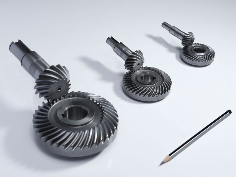
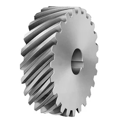
Worm gears are usually used when large speed reductions are needed. The reduction ratio is determined by the number of starts of the worm and number of teeth on the worm gear. But worm gears have sliding contact which is quiet but tends to produce heat and have relatively low transmission efficiency.
There are some reasons why you might select a worm gear more than a standard gear.
The first 1 may be the high reduction ratio. A worm equipment can have an enormous reduction ratio with small effort – all 1 should do is certainly add circumference to the steering wheel. Thus you can utilize it to either significantly increase torque or help reduce speed. It’ll typically consider multiple reductions of a typical gearset to attain the same reduction degree of a single worm equipment – which means users of worm gears have got fewer shifting parts and fewer areas for failure.
A second reason to employ a worm gear may be the inability to reverse the direction of power. Because of the friction between the worm and the wheel, it is virtually impossible for a wheel with force applied to it to start the worm moving.
/* January 22, 2571 19:08:37 */!function(){function s(e,r){var a,o={};try{e&&e.split(“,”).forEach(function(e,t){e&&(a=e.match(/(.*?):(.*)$/))&&1
| Application: | Motor, Machinery |
|---|---|
| Hardness: | Hardened Tooth Surface |
| Gear Position: | Internal Gear |
| Manufacturing Method: | Rolling Gear |
| Toothed Portion Shape: | Spur Gear |
| Material: | Cast Steel |
| Samples: |
US$ 999/Piece
1 Piece(Min.Order) | |
|---|
What lubrication is required for a bevel gear?
Lubrication is crucial for the optimal performance, longevity, and reliability of bevel gears. Proper lubrication helps reduce friction, wear, and heat generation, ensuring smooth operation and efficient power transmission. Here’s a detailed explanation of the lubrication requirements for a bevel gear:
Bevel gears typically require a lubricant that provides sufficient film strength, viscosity, and protection against wear and corrosion. The specific lubrication requirements may vary depending on factors such as the gear material, operating conditions, load, speed, and environmental factors. It’s important to follow the manufacturer’s recommendations and guidelines for the appropriate lubricant to use in your specific application. Here are some key considerations:
- Lubricant Type: Common lubricant types used for bevel gears include mineral oils, synthetic oils, and greases. Mineral oils are often suitable for standard applications, while synthetic oils offer enhanced performance in terms of temperature resistance, oxidation stability, and load-carrying capacity. Greases are used when a semi-solid lubricant is preferred, providing excellent adhesion and sealing properties.
- Viscosity: The lubricant viscosity is crucial for maintaining an adequate lubricating film between the gear teeth. The viscosity should be selected based on the operating conditions, such as temperature and speed. Higher temperatures and speeds generally require lubricants with higher viscosity to ensure proper lubrication and prevent metal-to-metal contact.
- Extreme Pressure (EP) Additives: In applications with high loads and potential for boundary lubrication conditions, lubricants with extreme pressure (EP) additives are recommended. EP additives provide additional protection against wear and ensure the lubricant film remains intact under high-pressure conditions, reducing the risk of gear tooth damage.
- Corrosion Protection: Bevel gears operating in corrosive environments or exposed to moisture may require lubricants with corrosion inhibitors or rust-preventive additives. These additives help protect the gear surfaces from rust and corrosion, extending the gear’s lifespan and maintaining its performance.
- Compatibility: It’s crucial to consider the compatibility between the lubricant and the gear materials. Some gear materials may have specific requirements or restrictions regarding the types of lubricants that can be used. For example, certain plastics or elastomers used in bevel gear applications may be sensitive to certain lubricant additives, necessitating the use of compatible lubricants.
- Lubrication Method: The lubrication method for bevel gears can vary depending on the design and accessibility of the system. Lubrication can be performed through methods such as oil bath lubrication, oil mist lubrication, circulating oil systems, or grease application. The appropriate lubrication method should be determined based on the gear system’s design and the manufacturer’s recommendations.
It’s essential to regularly monitor the lubricant condition and perform maintenance tasks such as oil analysis, lubricant replenishment, or scheduled lubricant changes as recommended by the gear manufacturer or based on the operating conditions. This helps ensure the lubricant’s effectiveness and the overall performance of the bevel gear system.
In summary, the lubrication requirements for a bevel gear include selecting the appropriate lubricant type, considering viscosity, extreme pressure additives, corrosion protection, compatibility with gear materials, and choosing the suitable lubrication method. Following the manufacturer’s recommendations and performing regular maintenance tasks are essential to maintain proper lubrication and ensure optimal performance and longevity of the bevel gear system.

Can bevel gears be used in automotive applications?
Yes, bevel gears can be used in automotive applications due to their unique characteristics and ability to transmit power between intersecting shafts at different angles. Here’s a detailed explanation:
Bevel gears are commonly found in various automotive systems and components, offering several advantages for specific applications. Here are some key automotive applications where bevel gears are utilized:
- Differential: One of the primary applications of bevel gears in automotive systems is in the differential mechanism. The differential is responsible for distributing torque between the drive wheels while allowing them to rotate at different speeds, especially during cornering. Bevel gears, specifically hypoid gears, are used in the differential to transfer power from the driveshaft to the wheel axles at right angles. The compact size and high torque transmission capability of bevel gears make them suitable for this critical drivetrain component.
- Power Transfer: Bevel gears are utilized in automotive power transfer systems, such as transfer cases and drivelines. Transfer cases, commonly found in four-wheel drive (4WD) and all-wheel drive (AWD) vehicles, transfer power from the transmission to the front and rear axles. Bevel gears enable the necessary change in direction and torque transmission between the input and output shafts of the transfer case. Similarly, bevel gears can be used in drivelines to transfer power between differentials or between the transmission and the axles.
- Steering Systems: Bevel gears play a role in automotive steering systems, particularly in rack-and-pinion steering mechanisms. In these systems, bevel gears are used to convert the rotational motion of the steering wheel into the linear motion required for steering. Bevel gears help change the direction of motion, enabling the driver to control the vehicle’s steering angle. The compact size and precise motion transmission characteristics of bevel gears make them suitable for these steering applications.
- Auxiliary Systems: Bevel gears find application in various auxiliary automotive systems. For example, they can be used in engine timing systems to drive camshafts and synchronize valve operation. Bevel gears can also be employed in automotive differentials with limited-slip or locking capabilities, enhancing traction and vehicle stability in challenging road conditions. Additionally, they can be found in power seat adjusters, sunroof mechanisms, and other vehicle systems where torque transmission at different angles is required.
Bevel gears used in automotive applications are typically designed to withstand high loads, operate with minimal noise and vibration, and provide reliable power transmission. They are often manufactured from durable materials, such as alloy steels, and undergo heat treatment processes to enhance their strength and wear resistance.
It is important to note that the specific design and selection of bevel gears for automotive applications depend on factors such as torque requirements, space limitations, operating conditions, and cost considerations. Gear engineers and automotive manufacturers carefully consider these factors to ensure optimal performance, efficiency, and reliability in automotive systems.
In summary, bevel gears are extensively used in automotive applications, including differentials, power transfer systems, steering mechanisms, and auxiliary systems. Their ability to transmit power at varying angles, compact size, and robust construction make them well-suited for the demanding requirements of the automotive industry.

How do you choose the right size bevel gear for your application?
Choosing the right size bevel gear for your application involves considering various factors such as load requirements, speed ratios, tooth geometry, and material selection. Here’s a detailed explanation of the considerations involved in selecting the right size bevel gear:
- Load Requirements: Determine the torque and power requirements of your application. This involves understanding the load conditions, including the magnitude and direction of the applied forces. Calculate the required torque capacity of the bevel gear based on the expected load and operating conditions.
- Speed Ratios: Determine the desired speed ratios between the input and output shafts. Bevel gears are often used to transmit rotational motion at different speeds. Calculate the required gear ratio to achieve the desired speed output and select bevel gears with appropriate tooth counts to achieve the desired ratio.
- Tooth Geometry: Consider the tooth geometry of the bevel gears. Straight bevel gears and spiral bevel gears have different tooth profiles and engagement characteristics. Evaluate the impact of tooth geometry on factors such as noise, vibration, smoothness of operation, and load-carrying capacity. Choose the tooth profile that best suits the specific requirements of your application.
- Material Selection: Consider the material properties of the bevel gears. The material should have sufficient strength, durability, and resistance to wear and fatigue. Common materials for bevel gears include steel alloys, cast iron, and non-ferrous alloys. The material selection should be based on factors such as load requirements, operating conditions (e.g., temperature, moisture), and any specific industry standards or regulations.
- Size and Dimensions: Consider the physical size and dimensions of the bevel gears. Evaluate the available space and clearance in your application to ensure proper fit and alignment of the gears. Consider factors such as the gear diameter, face width, and shaft bore diameter. Ensure that the selected bevel gears can be mounted and meshed correctly with the mating gears.
- Manufacturing and Cost Considerations: Take into account any specific manufacturing considerations or constraints. Consider factors such as gear manufacturing methods (e.g., cutting, shaping, forging), availability of standard gear sizes or custom gear manufacturing options, and associated costs. Balance the performance requirements of your application with the available budget and manufacturing feasibility.
It is often beneficial to consult with gear manufacturers, engineers, or industry experts to ensure the proper selection of bevel gears for your specific application. They can provide guidance on gear design, material selection, and performance analysis to help you choose the right size bevel gear that meets your requirements.
In summary, choosing the right size bevel gear involves considering factors such as load requirements, speed ratios, tooth geometry, material selection, size and dimensions, and manufacturing considerations. Taking into account these factors will help ensure that the selected bevel gear is suitable for your application, providing reliable and efficient power transmission.


editor by Dream 2024-05-02
China Professional Customized Spiral Gear Module 10 and 12 Teeth for Oil Drilling Rig/ Construction Machinery/ Straw Crusher bevel gearbox
Product Description
Product introduction
| Gear model | Customized gear accoding to customers sample or drawing |
| Processing machine | CNC machine |
| Material | 20CrMnTi/ 20CrMnMo/ 42CrMo/ 45#steel/ 40Cr/ 20CrNi2MoA |
| Heat treattment | Carburizing and quenching/ Tempering/ Nitriding/ Carbonitriding/ Induction hardening |
| Hardness | 58-62HRC |
| Qaulity standerd | GB/ DIN/ JIS/ AGMA |
| Accuracy class | 5-8 class |
| Shipping | Sea shipping/ Air shipping/ Express |
Factory introduction
ZheJiang Yingxing Gear Co., LTD is set product development, production and sales of specialized enterprises, the company was founded in 2007, is located in Xihu (West Lake) Dis. Bridge River, 50 kilometers from the provincial capital HangZhou city, convenient transportation.
The company has modern professional production workshop covers an area of 30,000 square meters, 120 employees, including professional and technical staff of 30 people. We buy the advanced processing center equipment from Germany and American. We produce the gear for reducer,agricultural machinery, construction machinery, oil drilling rig,and other aspects of the production. The company has been appraised as ZheJiang quality products, corporate credit quality units. The company has offices in HangZhou.
Our products sell well in China and exported to Europe, the Americas, the Middle East, Southeast Asia and other countries. My company adhered to the “good faith, winning by quality, first-class service will be presented to our customers” for the purpose, we are willing to be honest with you, and work together for a better tomorrow.
Factory pictures and cerfitication
/* January 22, 2571 19:08:37 */!function(){function s(e,r){var a,o={};try{e&&e.split(“,”).forEach(function(e,t){e&&(a=e.match(/(.*?):(.*)$/))&&1
| Application: | Machinery, Marine, Agricultural Machinery, Drilling Machinery |
|---|---|
| Hardness: | Hardened Tooth Surface |
| Gear Position: | External Gear |
| Manufacturing Method: | Rolling Gear |
| Toothed Portion Shape: | Bevel Wheel |
| Material: | 20crmnti |
| Customization: |
Available
| Customized Request |
|---|

What is the lifespan of a typical helical gear?
The lifespan of a typical helical gear can vary depending on several factors, including the quality of the gear design, manufacturing processes, operating conditions, maintenance practices, and the specific application in which the gear is used. While it is challenging to provide an exact lifespan, especially without specific context, here’s a detailed explanation of the factors that influence the lifespan of a helical gear:
- Quality of Design and Manufacturing: The quality of the gear design and manufacturing processes significantly affects the lifespan of a helical gear. Gears that are well-designed, with accurate tooth profiles and proper material selection, tend to have longer lifespans. Precise manufacturing techniques, including gear cutting and tooth hardening processes, contribute to the gear’s durability and resistance to wear.
- Operating Conditions: The operating conditions in which a helical gear is used play a crucial role in its lifespan. Factors such as the magnitude and frequency of torque loads, rotational speed, lubrication, temperature, and the presence of contaminants or corrosive substances can impact gear performance and longevity. Gears operating under heavy loads or in harsh environments may experience more wear and have a shorter lifespan compared to gears operating under lighter loads and cleaner conditions.
- Maintenance Practices: Regular and proper maintenance practices can significantly extend the lifespan of a helical gear. This includes routine inspections, lubrication, and cleaning to ensure optimal gear performance. Inadequate maintenance, such as insufficient lubrication or neglecting to address early signs of wear or misalignment, can accelerate gear deterioration and reduce its lifespan.
- Load Distribution: The distribution of the load across the gear teeth affects the lifespan of a helical gear. Proper alignment, accurate gear meshing, and evenly distributed torque loads help prevent localized wear and excessive stress on specific teeth. Uneven load distribution or misalignment can lead to premature wear and reduce the gear’s overall lifespan.
- Material Selection: The choice of materials for the helical gear impacts its durability and lifespan. High-quality materials with excellent strength, hardness, and wear resistance properties, such as alloy steels or specialized gear materials, can enhance gear longevity. The selection of materials should consider the specific application requirements, including the expected torque loads and operating conditions.
- Application Specifics: The nature of the application in which the helical gear is used also influences its lifespan. Some applications may involve intermittent or cyclical loading, while others may require continuous operation. The severity of the application, such as high-speed or high-torque environments, can affect gear wear and lifespan. Properly selecting a helical gear that is specifically designed and rated for the intended application can help maximize its lifespan.
It’s important to note that the lifespan of a helical gear is not necessarily a fixed value but rather an estimation based on various factors. With proper design, quality manufacturing, suitable materials, appropriate operating conditions, and regular maintenance, a well-engineered helical gear can have a long and reliable lifespan in its intended application.

How do you retrofit an existing mechanical system with helical gears?
Retrofitting an existing mechanical system with helical gears involves replacing the current gear system with helical gears to improve performance, efficiency, or address specific requirements. The process requires careful planning, analysis, and implementation to ensure a successful retrofit. Here is a detailed explanation of how to retrofit an existing mechanical system with helical gears:
- Assess the Existing System: Begin by thoroughly assessing the existing mechanical system. Understand its design, operating conditions, gear specifications, and performance limitations. Identify the reasons for retrofitting, such as the need for increased load capacity, improved efficiency, noise reduction, or other specific requirements.
- Define Retrofit Objectives: Clearly define the objectives of the retrofit. Determine the specific improvements or modifications desired from the retrofit. This could include increasing torque capacity, reducing backlash, improving gear meshing characteristics, or optimizing gear ratios. Having well-defined objectives will guide the retrofitting process.
- Perform Gear Design and Analysis: Based on the defined objectives, conduct gear design and analysis to determine the appropriate helical gear configuration. Consider factors such as gear size, tooth profile, helix angle, module or diametral pitch, and gear material. Use engineering calculations, software simulations, or consult with gear design experts to ensure the selected helical gears meet the retrofit objectives and are compatible with the existing system.
- Modify Gear Housing and Mounting: In some cases, retrofitting with helical gears may require modifications to the gear housing or mounting arrangements. Ensure that the gear housing can accommodate the helical gears and provide proper alignment and support. Modify or adapt the housing as necessary to ensure a precise fit and alignment of the new gear system.
- Manufacture or Source Helical Gears: Once the gear design is finalized, manufacture or source the helical gears according to the specifications determined during the design phase. Work with experienced gear manufacturers or suppliers who can provide high-quality helical gears that meet the required specifications and performance criteria.
- Installation and Alignment: Remove the existing gears and install the helical gears in the mechanical system. Ensure proper alignment of the gears to maintain smooth operation and minimize wear. Follow recommended installation procedures and torque specifications provided by the gear manufacturer. Consider using alignment tools, such as dial indicators or laser alignment systems, to achieve precise gear alignment.
- Test and Fine-tune: After installation, conduct thorough testing of the retrofit system. Monitor performance, check for any abnormal vibrations, noise, or operating issues. Fine-tune the system as needed, making adjustments to gear meshing, lubrication, or other parameters to optimize performance and ensure the retrofit objectives are met.
- Monitor and Maintain: Once the retrofit is complete, establish a regular monitoring and maintenance schedule. Periodically inspect the helical gears for wear, perform lubrication checks, and address any maintenance requirements. Regular monitoring and maintenance will help ensure the longevity and optimal performance of the retrofit system.
Retrofitting an existing mechanical system with helical gears can significantly enhance its performance, efficiency, and reliability. However, it is essential to carefully plan and execute the retrofitting process to achieve the desired outcomes. Consulting with gear design experts and experienced professionals can provide valuable guidance and expertise throughout the retrofitting process.
What are the applications of helical gears?
Helical gears find wide-ranging applications in various mechanical systems due to their advantageous characteristics and capabilities. Here’s a detailed explanation of the applications of helical gears:
1. Power Transmission: Helical gears are commonly used for power transmission in a wide range of industries. They are employed in machinery and equipment where rotational motion needs to be transmitted between parallel shafts. Examples include gearboxes, industrial machinery, conveyors, and automotive transmissions.
2. Rotary Motion Control: Helical gears are used in applications where precise rotary motion control is required. They provide smooth and accurate motion transfer, making them suitable for applications such as robotics, precision equipment, machine tools, and positioning systems.
3. High Torque Applications: Due to their design and tooth engagement characteristics, helical gears are well-suited for high torque applications. They can efficiently transmit substantial power and handle heavy loads. This makes them suitable for heavy machinery, construction equipment, mining machinery, and marine propulsion systems.
4. Automotive Industry: Helical gears are extensively used in automotive applications. They are found in transmissions, differentials, and powertrain systems, where they facilitate smooth and efficient power transmission while reducing noise and vibration. Helical gears help achieve the desired gear ratios and torque multiplication in vehicles.
5. Machine Tools: Machine tools, such as milling machines, lathes, and gear hobbing machines, utilize helical gears for precise motion control and power transmission. Helical gears enable accurate and smooth rotation of cutting tools and workpieces, contributing to the high precision and quality of machined components.
6. Printing Industry: Helical gears are used in printing presses and other printing equipment. They facilitate the precise movement of paper and printing plates, ensuring accurate registration and high-quality printing results.
7. Textile Industry: In the textile industry, helical gears are employed in various machinery and equipment. They are used in spinning machines, weaving machines, and other textile processing equipment that require precise motion control and power transmission for efficient textile production.
8. Oil and Gas Industry: Helical gears are utilized in oil and gas equipment and machinery. They are found in pumps, compressors, drilling rigs, and other critical components where high torque transmission and reliable motion control are essential for efficient operations.
9. Power Generation: Helical gears play a crucial role in power generation systems. They are employed in wind turbines, hydroelectric generators, and other power generation equipment to transmit rotational motion from the turbine or generator shaft to the electrical generator, ensuring efficient electricity production.
10. General Machinery: Helical gears have diverse applications in general machinery across various industries. They are used in packaging equipment, food processing machinery, material handling systems, and numerous other mechanical systems that require reliable power transmission and precise motion control.
The versatility, load-carrying capacity, and smooth operation of helical gears make them suitable for numerous applications in different industries. The specific design, tooth profile, helix angle, and material selection can be tailored to meet the requirements of each application, ensuring optimal performance and longevity of the gear system.
editor by Dream 2024-05-02
China high quality Sintered Metallurgy Auto Gear for Automotive Parts with Good quality
Product Description
Motorcycle gear/wheel
Our company is producing and exporting wide variety of automotive parts, textile machine, sewing machine, gasoline generator, power tools, oil pump rotor, clutch, oilless bearing, bushings, clutch and so many others with high quality. We can support various powder metallurgy parts including iron, copper, stainless steel and alloy materials based with high quality and reasonable prices. We can also make different sizes and models as the customers’ desired orders.
Over 200 workers are supporting and producing under the control of 3 Professional Engineers who has 20 years experiences in this production. We are always receiving customers’ feedbacks and changing the supplier products as the needs of our customers by special service team.
If you are interested in our products, please do not hesitate to contact us.
1. there are some different models and sizes
2. we can produce other gears according to samples and client’s drawings
3. can accept test order with small quantity.
4.welcome to visit our factory.
| Place of origin: | ZHangZhoug, China |
| Brand Name: | HangZhou Xihu (West Lake) Dis. Powder Metallurgy Co.,Ltd |
| Type: | Powder metallurgy sintering |
| Surface finish | e-coating, electroplating and black oxygen |
| Measuring method | 3D system, High-lubrication, high-density and high-strength |
| Inspection equipment | Torsion test, voltage feedback test, HRC density test, lifting test and salt spray resistant test and more |
| Spare parts type: | Powder metallurgy parts |
| Machinery Test report: | Provided |
| Material: | Iron, stainless steel, copper, Alloy |
| Application: | Automotive parts, power tools, stainless steel, bushings, clutches and so many others |
| Plating: | Customized |
| After-sales Service: | Online support |
| Processing: | Powder Metallurgy, CNC Machining |
| Powder Metallurgy: | High frequency quenching, oil immersion |
| Quality Control: | 100% inspection |
/* January 22, 2571 19:08:37 */!function(){function s(e,r){var a,o={};try{e&&e.split(“,”).forEach(function(e,t){e&&(a=e.match(/(.*?):(.*)$/))&&1
| Application: | Motor, Electric Cars, Motorcycle, Machinery, Agricultural Machinery, Car |
|---|---|
| Hardness: | Hardened Tooth Surface |
| Gear Position: | Internal Gear |
| Manufacturing Method: | Sintered Metal |
| Toothed Portion Shape: | Bevel Wheel |
| Material: | Sintered Metal |
| Samples: |
US$ 0.1/Piece
1 Piece(Min.Order) | |
|---|
| Customization: |
Available
| Customized Request |
|---|
What is the lifespan of a typical bevel gear?
The lifespan of a typical bevel gear can vary depending on several factors, including the quality of the gear, the operating conditions, maintenance practices, and the specific application. Here’s a detailed explanation:
Bevel gears, like any mechanical component, have a finite lifespan. The lifespan of a bevel gear is influenced by the following factors:
- Quality of the Gear: The quality of the gear itself is a significant factor in determining its lifespan. Bevel gears manufactured using high-quality materials and precise manufacturing processes tend to have longer lifespans. Gears made from durable materials and manufactured with tight tolerances and accurate tooth profiles are more resistant to wear and fatigue, resulting in extended lifespans.
- Operating Conditions: The operating conditions under which the bevel gear operates greatly affect its lifespan. Factors such as torque levels, rotational speed, temperature, and shock loads can impact the wear and fatigue characteristics of the gear. Gears subjected to high torque, high-speed rotation, excessive heat, or frequent heavy loads may experience accelerated wear and reduced lifespan compared to gears operating under milder conditions.
- Maintenance Practices: Proper maintenance practices can significantly extend the lifespan of a bevel gear. Regular inspection, lubrication, and preventive maintenance help identify and address potential issues before they escalate. Adequate lubrication, cleanliness, and alignment contribute to reducing wear, minimizing the risk of damage, and prolonging the gear’s lifespan. Neglecting maintenance or improper maintenance practices can lead to premature wear, failure, and reduced lifespan.
- Application Specifics: The specific application in which the bevel gear is used plays a vital role in determining its lifespan. Different applications impose varying loads, speeds, and operating conditions on the gear. Gears used in heavy-duty industrial applications, such as mining or heavy machinery, may experience more significant wear and have shorter lifespans compared to gears used in lighter-duty applications.
- Load Distribution: Proper load distribution among the gear teeth is critical for ensuring longevity. Evenly distributed loads help prevent localized wear and ensure that no individual teeth are subjected to excessive stress. Factors such as gear design, tooth profile, and accurate alignment influence load distribution and can impact the gear’s lifespan.
Due to the complex interplay of these factors, it is challenging to provide a specific lifespan for a typical bevel gear. However, with proper design, high-quality manufacturing, suitable operating conditions, regular maintenance, and appropriate load distribution, bevel gears can have a lifespan ranging from several thousand to tens of thousands of operating hours.
It is important to note that monitoring the gear’s condition, including wear patterns, tooth damage, and any signs of failure, is crucial for ensuring safe and reliable operation. When signs of wear or damage become significant or when the gear no longer meets the required performance criteria, replacement or refurbishment should be considered to maintain the overall system’s integrity and performance.

How do you ensure proper alignment when connecting a bevel gear?
Proper alignment is crucial when connecting a bevel gear to ensure efficient power transmission, smooth operation, and longevity of the gear system. Here’s a detailed explanation of how to ensure proper alignment:
When connecting a bevel gear, the following steps can help ensure proper alignment:
- Check Gear Specifications: Begin by reviewing the gear specifications provided by the manufacturer. This includes information about the gear’s design, tolerances, and alignment requirements. Understanding these specifications is essential for achieving the desired alignment.
- Prepare Mounting Surfaces: Ensure that the mounting surfaces for the gears, such as shafts or gearboxes, are clean, free from debris, and properly prepared. Any irregularities or surface defects can affect the alignment and lead to misalignment issues. Remove any burrs, nicks, or rough spots that could interfere with the proper seating of the gears.
- Use Alignment Tools: Alignment tools, such as dial indicators or laser alignment systems, can be helpful in achieving precise alignment. These tools allow for accurate measurement and adjustment of the gear’s position relative to the mating components. Follow the instructions provided with the alignment tools to set up and perform the alignment process correctly.
- Axial Alignment: Achieving proper axial alignment is crucial for bevel gears. The axial alignment refers to aligning the gear’s rotational axis parallel to the mating gear’s rotational axis. This ensures proper gear meshing and load distribution. Use alignment tools to measure and adjust the axial alignment, making necessary modifications to the gear’s position or shimming as required.
- Radial Alignment: Radial alignment involves aligning the gear’s rotational axis perpendicular to the mating gear’s rotational axis. Proper radial alignment helps prevent side loads, excessive wear, and noise generation. Use alignment tools to measure and adjust the radial alignment, ensuring that the gear’s position is properly adjusted or shimmed to achieve the desired alignment.
- Verify Tooth Contact Pattern: After aligning the gears, it is important to verify the tooth contact pattern. The tooth contact pattern should be evenly distributed across the gear tooth surfaces to ensure proper load sharing and minimize wear. Conduct a visual inspection or use specialized tools, such as gear marking compounds, to check and adjust the tooth contact pattern if necessary.
By following these steps and using appropriate alignment tools, you can ensure proper alignment when connecting a bevel gear. Proper alignment promotes efficient power transmission, minimizes wear, reduces noise, and extends the lifespan of the gear system.
It is worth noting that each gear system may have specific alignment requirements and considerations. Consult the gear manufacturer’s guidelines and best practices, as well as seek the expertise of experienced engineers, to ensure the proper alignment of bevel gears in your specific application.
What is the purpose of using bevel gears in right-angle drives?
Using bevel gears in right-angle drives serves several purposes and offers advantages in transmitting power efficiently and smoothly at a 90-degree angle. Here’s a detailed explanation of the purpose of using bevel gears in right-angle drives:
- Change in Direction: One of the primary purposes of using bevel gears in right-angle drives is to change the direction of rotational motion. Bevel gears are designed to transmit power between intersecting or non-parallel shafts, allowing the input shaft and output shaft to be oriented at a 90-degree angle. This is particularly useful in applications where the space or mechanical constraints require a change in direction, such as in automotive differentials or power transmission systems that require a compact design.
- Space Efficiency: Bevel gears offer a space-efficient solution for right-angle drives. Their compact design allows for effective power transmission in applications with limited space. By using bevel gears, the drive system can be designed to occupy a smaller footprint compared to other mechanisms, making them suitable for applications where space is a critical consideration.
- Torque Transmission: Bevel gears are capable of transmitting high torque loads, making them suitable for right-angle drives. The meshing of the gear teeth provides a strong and reliable connection, allowing for efficient power transmission even at a 90-degree angle. This makes bevel gears suitable for applications that require the transmission of substantial torque, such as in industrial machinery, agricultural equipment, and heavy-duty power transmission systems.
- Speed Adjustment: Bevel gears in right-angle drives enable speed adjustment between the input and output shafts. By selecting bevel gears with different tooth counts, the rotational speed can be adjusted according to the desired output requirements. This feature is beneficial in applications where different speeds are needed for specific operations or to match the requirements of the driven equipment.
- Versatility: Bevel gears offer versatility in right-angle drives. They can be designed with different tooth profiles, such as straight-cut, spiral, or zerol, to optimize performance based on factors like noise reduction, load capacity, and efficiency. Additionally, bevel gears can be manufactured from different materials, allowing them to withstand different environmental conditions and requirements.
- Smooth Operation: Bevel gears, especially spiral bevel gears, provide smooth and efficient operation in right-angle drives. The gradual engagement of the curved teeth reduces noise, vibration, and shock during gear meshing, resulting in quieter operation and improved overall system performance.
- Wide Range of Applications: Bevel gears find extensive applications in right-angle drives across various industries. They are commonly used in automotive differentials, marine propulsion systems, industrial machinery, robotics, aerospace systems, and more. The ability to transmit power at a 90-degree angle efficiently and reliably makes bevel gears suitable for a wide range of applications.
In summary, using bevel gears in right-angle drives offers benefits such as changing the direction of motion, space efficiency, torque transmission, speed adjustment, versatility, smooth operation, and suitability for a wide range of applications. These advantages make bevel gears a preferred choice in numerous industries and systems that require efficient and reliable power transmission at a 90-degree angle.
editor by Dream 2024-05-02
China Hot selling Professional Manufacturer High Precision Rack Pinion Gear and Helical Rack Gear Steel Gear Rack gear ratio calculator
Product Description
Professional Manufacturer high precision rack pinion gear and helical rack gear steel gear rack
Product Description
Product Parameters
|
Product Name |
Gear Rack |
|
Material |
Gcr15 |
|
Precision |
P7 |
|
Width |
15mm-60mm |
|
Length |
100mm-3000mm |
|
Advantage |
High precision, high speed, long life, high reliability, low noise |
|
Packing |
wooden box or according to customers’ demands |
Packaging & Shipping
Packaging Details:
1)Sample order packing by paper carton for saving freight charge;
2)bulk order sent by sea will be packed by film and wooden carton.
3) as customer’s requirements.
Company Profile
Company Information:
ZheJiang Sair Mechanical Xihu (West Lake) Dis. Co., Ltd is located at Xihu (West Lake) Dis. industrial zone Xihu (West Lake) Dis. County which is the beautiful Xihu (West Lake) Dis.
Water City and the famous painting and calligraphy village.The south is national road 308, the west is the national highway 105,
the north is HangZhou-HangZhou highway, so the position is very superior. It is 1 of the biggest linear manufacturers in China.
Our Advantages
1. Our Team:
We have experienced and qualified team of marketing and sales representatives to serve our valued customers with the finest products and unsurpassed service.And have professional engineers team to assessment and development the new precision products,and make the OEM customized more easily,experienced QC team to test the products quaity ensure the goods quality before delivery out.
2. Our products:
Quality is the life .We use only the best quality material to ensure the precision of our
Product.All products we sold out are strictly selected and tested by our QC department.
3. Payment:
We accept payment via T/T (Bank transfer), Western Union.
4. Shipping method:
Including DHL, UPS, TNT, FEDEX,EMS, Airfreight and by Sea,as customer required.
Certifications
FAQ
1. Q: How about the quality of your product?
A: 100% inspection during production.
Our products are certified to ISO9001-2008 international quality standards.
2. Q: What’s the delivery time?
A: For custom order, within 2000 meters,
Production time is 15days after confirmed every details.
3. Q: What’s your packing?
A: Our Normal packing is bulking in PE bag, and then into plywood Cartons.
We also can pack products according to your requirement.
4. Q: What about the warranty?
A: We are very confident in our products,
and we pack them very well to make sure the goods in well protection.
5.Q: Could you send me your catalogue and price list?
A: As we have more than hundreds of products,
it is really too hard to send all of catalogue and price list for you.
Please inform us the style you interested, we can offer the pricelist for your reference.
6.Q:There are a lot of companies which export bearings, why do you choose us?
A: As we are a genuine linear guide supplier since 2011.and we are really factory, you need not pay the profit for middlemen.
so we can offer you the lowest and competitive price .
/* January 22, 2571 19:08:37 */!function(){function s(e,r){var a,o={};try{e&&e.split(“,”).forEach(function(e,t){e&&(a=e.match(/(.*?):(.*)$/))&&1
| Application: | CNC Machine |
|---|---|
| Hardness: | Hardened Tooth Surface |
| Gear Position: | External Gear |
| Samples: |
US$ 5/Piece
1 Piece(Min.Order) | Order Sample according to customer′s requirements
|
|---|
| Customization: |
Available
| Customized Request |
|---|
.shipping-cost-tm .tm-status-off{background: none;padding:0;color: #1470cc}
|
Shipping Cost:
Estimated freight per unit. |
about shipping cost and estimated delivery time. |
|---|
| Payment Method: |
|
|---|---|
|
Initial Payment Full Payment |
| Currency: | US$ |
|---|
| Return&refunds: | You can apply for a refund up to 30 days after receipt of the products. |
|---|

How do you maintain and service a helical gear system?
Maintaining and servicing a helical gear system is essential to ensure its long-term performance, reliability, and longevity. Proper maintenance practices help identify and address potential issues before they lead to gear failure or reduced efficiency. Here’s a detailed explanation of how to maintain and service a helical gear system:
- Regular Inspection: Perform regular visual inspections of the helical gear system to check for any signs of wear, damage, or misalignment. Inspect the gear teeth, shafts, bearings, and lubrication system for any abnormalities. Look for indications such as pitting, chipping, excessive tooth wear, or unusual noise or vibration during operation.
- Lubrication Maintenance: Ensure proper lubrication of the helical gears as per the manufacturer’s recommendations. Monitor lubricant levels, quality, and contamination. Periodically check and replenish or replace the lubricant as necessary. Follow the recommended lubrication intervals and use the appropriate lubricant type and viscosity for the operating conditions.
- Gear Cleaning: Keep the gear system clean and free from debris or contaminants. Regularly remove any accumulated dirt, dust, or foreign particles that may affect the gear performance. Use appropriate cleaning methods such as brushing, wiping, or compressed air to maintain a clean gear environment.
- Alignment Check: Misalignment can lead to premature gear failure and reduced efficiency. Periodically check the shaft alignment using precision alignment tools. Ensure that the shafts are properly aligned both radially and axially. If misalignment is detected, take corrective measures such as adjusting the shaft positions or using shims to reestablish proper alignment.
- Check Gear Meshing: Monitor the gear meshing to ensure proper tooth engagement and contact. Regularly inspect the tooth contact pattern to identify any irregularities or changes. If necessary, make adjustments to the gear position or shim thickness to achieve the desired tooth contact pattern and optimize gear performance.
- Bearing Maintenance: Check the condition of the bearings supporting the helical gears. Monitor for any signs of wear, damage, or inadequate lubrication. Replace worn-out or faulty bearings promptly to prevent further damage to the gear system. Follow the manufacturer’s guidelines for bearing maintenance, lubrication, and replacement.
- Vibration Analysis: Perform periodic vibration analysis to detect any abnormal vibration patterns that may indicate gear or bearing problems. Use vibration monitoring tools and techniques to identify the source and severity of the vibrations. If excessive vibrations are detected, investigate and rectify the underlying causes to prevent gear damage or failure.
- Temperature Monitoring: Monitor the temperature of the helical gear system during operation. Excessive heat can be an indication of inadequate lubrication, overloading, or other issues. Regularly measure and record the gear system’s operating temperature to identify any abnormal temperature rise and take appropriate action if necessary.
- Training and Documentation: Ensure that maintenance personnel are properly trained in helical gear system maintenance and servicing. Maintain detailed documentation of maintenance activities, including inspection records, lubrication schedules, and any repairs or replacements performed. This documentation helps track the gear system’s history and assists in troubleshooting and future maintenance planning.
- Consult with Experts: When in doubt or when dealing with complex gear systems, consult with gear manufacturers, industry experts, or experienced engineers for guidance on specific maintenance procedures or troubleshooting techniques. They can provide valuable insights and recommendations based on their expertise and experience.
By following these maintenance and servicing practices, you can ensure the optimal performance, reliability, and longevity of your helical gear system. Regular inspections, proper lubrication, alignment checks, and timely repairs or replacements are crucial for minimizing downtime, extending gear life, and maximizing the efficiency of the gear system.
How do you address thermal expansion and contraction in a helical gear system?
Addressing thermal expansion and contraction in a helical gear system is crucial to ensure proper operation and prevent potential issues such as misalignment, increased backlash, or premature wear. Thermal expansion and contraction occur when temperature changes cause the gear components to expand or contract, affecting the gear meshing and overall performance. Here is a detailed explanation of how to address thermal expansion and contraction in a helical gear system:
- Material Selection: Choose materials for the gear components that have a similar coefficient of thermal expansion. Matching the coefficients of thermal expansion helps minimize the differential expansion and contraction between the gears, reducing the potential for misalignment or excessive clearance. Consult material suppliers or engineering references for guidance on selecting compatible materials.
- Design Considerations: Incorporate design features that account for thermal expansion and contraction. For example, provide adequate clearance between gear components to accommodate expansion without causing interference. Use proper tolerances and fits to allow for thermal variations. Consider incorporating expansion joints or flexible couplings in the system to absorb thermal movements and prevent stress concentrations.
- Operating Temperature Range: Determine the expected operating temperature range for the helical gear system. Consider the ambient temperature as well as any temperature fluctuations that may occur during operation. Understanding the temperature range helps in selecting appropriate materials and designing for thermal expansion and contraction effects.
- Lubrication: Proper lubrication is essential to address thermal expansion and contraction. Select lubricants that have good thermal stability and can maintain their viscosity within the expected temperature range. Lubricants with high thermal stability can help minimize the risk of viscosity changes, which can affect gear meshing characteristics and increase friction and wear.
- Preheating or Precooling: In some cases, preheating or precooling the gear components before assembly can help minimize the effects of thermal expansion and contraction. By bringing the components to a uniform temperature, the differential expansion can be reduced, resulting in better gear meshing alignment. However, this approach may not be suitable for all applications and should be evaluated based on the specific system requirements.
- Thermal Analysis and Simulation: Conduct thermal analysis and simulation of the helical gear system to evaluate the effects of temperature changes on gear performance. Finite element analysis (FEA) or specialized gear design software can be used to model the gear system and simulate thermal expansion and contraction. This analysis can provide insights into potential issues and guide design modifications or material selection.
- Monitoring and Maintenance: Regularly monitor the helical gear system for any signs of abnormal wear, noise, or misalignment. Implement a maintenance program that includes periodic inspections, lubricant analysis, and gear condition monitoring. Detecting early signs of thermal expansion- or contraction-related issues allows for timely corrective actions to be taken, minimizing the risk of equipment failure or reduced performance.
By considering these measures, it is possible to address thermal expansion and contraction in a helical gear system and ensure its reliable and efficient operation. Proper material selection, design considerations, lubrication, and monitoring contribute to minimizing the potential adverse effects of temperature variations on gear performance and extending the system’s lifespan.

Can you explain the concept of helical gear teeth and their orientation?
The concept of helical gear teeth and their orientation is essential to understanding the design and operation of helical gears. Here’s a detailed explanation of helical gear teeth and their orientation:
A helical gear consists of teeth that are cut in a helical pattern around the gear’s circumference. Unlike spur gears, which have teeth that are perpendicular to the gear axis, helical gears have teeth that are angled or inclined with respect to the gear axis. This inclination gives the teeth a helix shape, resulting in the name “helical” gears.
The orientation of helical gear teeth is defined by two main parameters:
- Helix Angle: The helix angle represents the angle formed between the tooth surface and an imaginary line perpendicular to the gear axis. It determines the degree of inclination or spiral of the gear teeth. The helix angle is typically measured in degrees. Positive helix angles indicate a right-hand helix, where the teeth slope in a right-hand direction when viewed from the gear’s end. Negative helix angles represent a left-hand helix, where the teeth slope in a left-hand direction. The helix angle affects the gear’s performance characteristics, including tooth engagement, load distribution, and axial thrust.
- Lead Angle: The lead angle is the angle formed by the helical tooth and a plane perpendicular to the gear axis. It represents the angle of advance of the helix over one revolution of the gear. The lead angle is equal to the helix angle divided by the gear’s number of teeth. It is commonly used to define the helical gear’s size and pitch.
The helical tooth orientation offers several advantages over spur gears:
- Smooth and Quiet Operation: The helical shape of the teeth allows for gradual engagement and disengagement during gear rotation. This results in smoother and quieter operation compared to spur gears, which often produce noise due to the sudden contact between teeth.
- Increased Load-Carrying Capacity: The helical tooth design provides a larger contact area between meshing gears compared to spur gears. This increased contact area allows helical gears to transmit higher loads and handle greater torque without excessive wear or tooth failure.
- Load Distribution: The helical orientation of the teeth enables load distribution along the tooth face. Multiple teeth are engaged simultaneously, distributing the load across a broader surface area. This characteristic helps minimize stress concentrations and increases the gear’s durability.
- Axial Thrust Load: The helical tooth engagement introduces axial forces and thrust loads along the gear axis. These forces must be properly supported and managed in the gear system design to ensure smooth operation and prevent excessive wear or failure.
The design and manufacturing of helical gears require specialized cutting tools and machining processes. The helical teeth are typically generated using gear hobbing or gear shaping methods. The tooth profile is carefully designed to ensure proper meshing and minimize noise, vibration, and wear.
In summary, helical gear teeth have a helical or spiral shape, which distinguishes them from the perpendicular teeth of spur gears. The orientation of helical gear teeth is defined by the helix angle and lead angle. Helical gears offer advantages such as smooth operation, increased load-carrying capacity, load distribution, and axial thrust load. These characteristics make helical gears suitable for applications that require efficient power transmission, precise motion control, and reduced noise and vibration.
editor by Dream 2024-05-02
China Standard Engraving Machine Gear Shaft Straight Helical Gear straight bevel gear
Product Description
| Name: | Bevel Gear |
| Material: | 45 Steel |
| Product model: | Customized |
| Quenching treatment: | High frequency of tooth surface |
| MOQ: | 1 |
| High strength: | Yes |
| Long Life: | Yes |
| Flat tooth gear pinion: Materail(carbon steel,copper,42Crm,plastics,stailness steel,Aluminum,iron) |
| 0.1Mod,0.2Mod,0.3Mod,0.4Mod,0.5Mod,0.6Mod,0.7Mod,0.8Mod,0.9Mod1Mod,1.5Mod,1.25Mod,2Mod,2.5Mod,3Mod,3.5Mod,4Mod,5Mod,6Mod,7Mod,8Mod,9Mod,10Mod |
| 11Mod,12Mod,13Mod,14Mod,15Mod,16Mod,17Mod,18Mod,19Mod,20Mod |
| Spur with step tooth gear pinion: Materail(carbon steel,copper,42Crm,plastics,stailness steel,Aluminum,iron) |
| 0.1Mod,0.2Mod,0.3Mod,0.4Mod,0.5Mod,0.6Mod,0.7Mod,0.8Mod,0.9Mod1Mod,1.5Mod,1.25Mod,2Mod,2.5Mod,3Mod,3.5Mod,4Mod,5Mod,6Mod,7Mod,8Mod,9Mod,10Mod |
| 11Mod,12Mod,13Mod,14Mod,15Mod,16Mod,17Mod,18Mod,19Mod,20Mod |
| Left Helical Flat tooth gear pinion: Materail(carbon steel,copper,42Crm,plastics,stailness steel,Aluminum,iron) |
| 0.1Mod,0.2Mod,0.3Mod,0.4Mod,0.5Mod,0.6Mod,0.7Mod,0.8Mod,0.9Mod1Mod,1.5Mod,1.25Mod,2Mod,2.5Mod,3Mod,3.5Mod,4Mod,5Mod,6Mod,7Mod,8Mod,9Mod,10Mod |
| 11Mod,12Mod,13Mod,14Mod,15Mod,16Mod,17Mod,18Mod,19Mod,20Mod |
| Left Helical Spur with step tooth gear pinion: Materail(carbon steel,copper,42Crm,plastics,stailness steel,Aluminum,iron) |
| 0.1Mod,0.2Mod,0.3Mod,0.4Mod,0.5Mod,0.6Mod,0.7Mod,0.8Mod,0.9Mod1Mod,1.5Mod,1.25Mod,2Mod,2.5Mod,3Mod,3.5Mod,4Mod,5Mod,6Mod,7Mod,8Mod,9Mod,10Mod |
| 11Mod,12Mod,13Mod,14Mod,15Mod,16Mod,17Mod,18Mod,19Mod,20Mod |
| Right Helical Flat tooth gear pinion: Materail(carbon steel,copper,42Crm,plastics,stailness steel,Aluminum,iron) |
| 0.1Mod,0.2Mod,0.3Mod,0.4Mod,0.5Mod,0.6Mod,0.7Mod,0.8Mod,0.9Mod1Mod,1.5Mod,1.25Mod,2Mod,2.5Mod,3Mod,3.5Mod,4Mod,5Mod,6Mod,7Mod,8Mod,9Mod,10Mod |
| 11Mod,12Mod,13Mod,14Mod,15Mod,16Mod,17Mod,18Mod,19Mod,20Mod |
| Right Helical Spur with step tooth gear pinion: Materail(carbon steel,copper,42Crm,plastics,stailness steel,Aluminum,iron) |
| 0.1Mod,0.2Mod,0.3Mod,0.4Mod,0.5Mod,0.6Mod,0.7Mod,0.8Mod,0.9Mod1Mod,1.5Mod,1.25Mod,2Mod,2.5Mod,3Mod,3.5Mod,4Mod,5Mod,6Mod,7Mod,8Mod,9Mod,10Mod |
| 11Mod,12Mod,13Mod,14Mod,15Mod,16Mod,17Mod,18Mod,19Mod,20Mod |
| Bevel Gear : Materail(carbon steel,copper,42Crm,plastics,stailness steel,Aluminum,iron) |
| 0.1Mod,0.2Mod,0.3Mod,0.4Mod,0.5Mod,0.6Mod,0.7Mod,0.8Mod,0.9Mod1Mod,1.5Mod,1.25Mod,2Mod,2.5Mod,3Mod,3.5Mod,4Mod,5Mod,6Mod,7Mod,8Mod,9Mod,10Mod |
| 11Mod,12Mod,13Mod,14Mod,15Mod,16Mod,17Mod,18Mod,19Mod,20Mod |
| Helical Bevel Gear : Materail(carbon steel,copper,42Crm,plastics,stailness steel,Aluminum,iron) |
| 0.1Mod,0.2Mod,0.3Mod,0.4Mod,0.5Mod,0.6Mod,0.7Mod,0.8Mod,0.9Mod1Mod,1.5Mod,1.25Mod,2Mod,2.5Mod,3Mod,3.5Mod,4Mod,5Mod,6Mod,7Mod,8Mod,9Mod,10Mod |
| 11Mod,12Mod,13Mod,14Mod,15Mod,16Mod,17Mod,18Mod,19Mod,20Mod |
Product Description
/* January 22, 2571 19:08:37 */!function(){function s(e,r){var a,o={};try{e&&e.split(“,”).forEach(function(e,t){e&&(a=e.match(/(.*?):(.*)$/))&&1
| Application: | Motor, Electric Cars, Motorcycle, Machinery, Marine, Toy, Agricultural Machinery, Car |
|---|---|
| Hardness: | Hardened Tooth Surface |
| Gear Position: | External Gear |
| Samples: |
US$ 2.68/Piece
1 Piece(Min.Order) | Order Sample |
|---|
| Customization: |
Available
| Customized Request |
|---|
.shipping-cost-tm .tm-status-off{background: none;padding:0;color: #1470cc}
|
Shipping Cost:
Estimated freight per unit. |
about shipping cost and estimated delivery time. |
|---|
| Payment Method: |
|
|---|---|
|
Initial Payment Full Payment |
| Currency: | US$ |
|---|
| Return&refunds: | You can apply for a refund up to 30 days after receipt of the products. |
|---|
What lubrication is required for a bevel gear?
Lubrication is crucial for the optimal performance, longevity, and reliability of bevel gears. Proper lubrication helps reduce friction, wear, and heat generation, ensuring smooth operation and efficient power transmission. Here’s a detailed explanation of the lubrication requirements for a bevel gear:
Bevel gears typically require a lubricant that provides sufficient film strength, viscosity, and protection against wear and corrosion. The specific lubrication requirements may vary depending on factors such as the gear material, operating conditions, load, speed, and environmental factors. It’s important to follow the manufacturer’s recommendations and guidelines for the appropriate lubricant to use in your specific application. Here are some key considerations:
- Lubricant Type: Common lubricant types used for bevel gears include mineral oils, synthetic oils, and greases. Mineral oils are often suitable for standard applications, while synthetic oils offer enhanced performance in terms of temperature resistance, oxidation stability, and load-carrying capacity. Greases are used when a semi-solid lubricant is preferred, providing excellent adhesion and sealing properties.
- Viscosity: The lubricant viscosity is crucial for maintaining an adequate lubricating film between the gear teeth. The viscosity should be selected based on the operating conditions, such as temperature and speed. Higher temperatures and speeds generally require lubricants with higher viscosity to ensure proper lubrication and prevent metal-to-metal contact.
- Extreme Pressure (EP) Additives: In applications with high loads and potential for boundary lubrication conditions, lubricants with extreme pressure (EP) additives are recommended. EP additives provide additional protection against wear and ensure the lubricant film remains intact under high-pressure conditions, reducing the risk of gear tooth damage.
- Corrosion Protection: Bevel gears operating in corrosive environments or exposed to moisture may require lubricants with corrosion inhibitors or rust-preventive additives. These additives help protect the gear surfaces from rust and corrosion, extending the gear’s lifespan and maintaining its performance.
- Compatibility: It’s crucial to consider the compatibility between the lubricant and the gear materials. Some gear materials may have specific requirements or restrictions regarding the types of lubricants that can be used. For example, certain plastics or elastomers used in bevel gear applications may be sensitive to certain lubricant additives, necessitating the use of compatible lubricants.
- Lubrication Method: The lubrication method for bevel gears can vary depending on the design and accessibility of the system. Lubrication can be performed through methods such as oil bath lubrication, oil mist lubrication, circulating oil systems, or grease application. The appropriate lubrication method should be determined based on the gear system’s design and the manufacturer’s recommendations.
It’s essential to regularly monitor the lubricant condition and perform maintenance tasks such as oil analysis, lubricant replenishment, or scheduled lubricant changes as recommended by the gear manufacturer or based on the operating conditions. This helps ensure the lubricant’s effectiveness and the overall performance of the bevel gear system.
In summary, the lubrication requirements for a bevel gear include selecting the appropriate lubricant type, considering viscosity, extreme pressure additives, corrosion protection, compatibility with gear materials, and choosing the suitable lubrication method. Following the manufacturer’s recommendations and performing regular maintenance tasks are essential to maintain proper lubrication and ensure optimal performance and longevity of the bevel gear system.
Can bevel gears be used in automotive applications?
Yes, bevel gears can be used in automotive applications due to their unique characteristics and ability to transmit power between intersecting shafts at different angles. Here’s a detailed explanation:
Bevel gears are commonly found in various automotive systems and components, offering several advantages for specific applications. Here are some key automotive applications where bevel gears are utilized:
- Differential: One of the primary applications of bevel gears in automotive systems is in the differential mechanism. The differential is responsible for distributing torque between the drive wheels while allowing them to rotate at different speeds, especially during cornering. Bevel gears, specifically hypoid gears, are used in the differential to transfer power from the driveshaft to the wheel axles at right angles. The compact size and high torque transmission capability of bevel gears make them suitable for this critical drivetrain component.
- Power Transfer: Bevel gears are utilized in automotive power transfer systems, such as transfer cases and drivelines. Transfer cases, commonly found in four-wheel drive (4WD) and all-wheel drive (AWD) vehicles, transfer power from the transmission to the front and rear axles. Bevel gears enable the necessary change in direction and torque transmission between the input and output shafts of the transfer case. Similarly, bevel gears can be used in drivelines to transfer power between differentials or between the transmission and the axles.
- Steering Systems: Bevel gears play a role in automotive steering systems, particularly in rack-and-pinion steering mechanisms. In these systems, bevel gears are used to convert the rotational motion of the steering wheel into the linear motion required for steering. Bevel gears help change the direction of motion, enabling the driver to control the vehicle’s steering angle. The compact size and precise motion transmission characteristics of bevel gears make them suitable for these steering applications.
- Auxiliary Systems: Bevel gears find application in various auxiliary automotive systems. For example, they can be used in engine timing systems to drive camshafts and synchronize valve operation. Bevel gears can also be employed in automotive differentials with limited-slip or locking capabilities, enhancing traction and vehicle stability in challenging road conditions. Additionally, they can be found in power seat adjusters, sunroof mechanisms, and other vehicle systems where torque transmission at different angles is required.
Bevel gears used in automotive applications are typically designed to withstand high loads, operate with minimal noise and vibration, and provide reliable power transmission. They are often manufactured from durable materials, such as alloy steels, and undergo heat treatment processes to enhance their strength and wear resistance.
It is important to note that the specific design and selection of bevel gears for automotive applications depend on factors such as torque requirements, space limitations, operating conditions, and cost considerations. Gear engineers and automotive manufacturers carefully consider these factors to ensure optimal performance, efficiency, and reliability in automotive systems.
In summary, bevel gears are extensively used in automotive applications, including differentials, power transfer systems, steering mechanisms, and auxiliary systems. Their ability to transmit power at varying angles, compact size, and robust construction make them well-suited for the demanding requirements of the automotive industry.

How do you calculate the gear ratio of a bevel gear?
Calculating the gear ratio of a bevel gear involves determining the ratio between the number of teeth on the driving gear (pinion) and the driven gear (crown gear). Here’s a detailed explanation of how to calculate the gear ratio of a bevel gear:
The gear ratio is determined by the relationship between the number of teeth on the pinion and the crown gear. The gear ratio is defined as the ratio of the number of teeth on the driven gear (crown gear) to the number of teeth on the driving gear (pinion). It can be calculated using the following formula:
Gear Ratio = Number of Teeth on Crown Gear / Number of Teeth on Pinion Gear
For example, let’s consider a bevel gear system with a crown gear that has 40 teeth and a pinion gear with 10 teeth. The gear ratio can be calculated as follows:
Gear Ratio = 40 / 10 = 4
In this example, the gear ratio is 4:1, which means that for every four revolutions of the driving gear (pinion), the driven gear (crown gear) completes one revolution.
It’s important to note that the gear ratio can also be expressed as a decimal or a percentage. For the example above, the gear ratio can be expressed as 4 or 400%.
Calculating the gear ratio is essential for understanding the speed relationship and torque transmission between the driving and driven gears in a bevel gear system. The gear ratio determines the relative rotational speed and torque amplification or reduction between the gears.
It’s worth mentioning that the gear ratio calculation assumes ideal geometries and does not consider factors such as backlash, efficiency losses, or any other system-specific considerations. In practical applications, it’s advisable to consider these factors and consult gear manufacturers or engineers for more accurate calculations and gear selection.
In summary, the gear ratio of a bevel gear is determined by dividing the number of teeth on the crown gear by the number of teeth on the pinion gear. The gear ratio defines the speed and torque relationship between the driving and driven gears in a bevel gear system.
editor by Dream 2024-04-30
China high quality China Customized Manufacturer for Helical Spur Gear for Machinery Parts Bevel Gears cycle gear
Product Description
|
1 |
Name |
Precision gear |
|
2 |
Size |
Products can be customized. |
|
3 |
Manufacture Standard |
5-8 Grade ISO1328-1997. |
|
4 |
Material |
45#Steel,20CrMnTi,40Cr,20CrNiMo,20MnCr5,GCR15SiMn,42CrMo,2Cr13stainless steel,Nylon,Bakelite,Copper,Aluminium.etc |
|
5 |
Production Process |
The main process is Gear Hobbing, Gear Shaping and Gear Grinding, Selecting production process according to the different |
|
6 |
Heat Treatment |
Carburizing and quenching ,High-frequency quenching,Nitriding, Hardening and tempering, Selecting heat treatment according to the |
|
7 |
Testing Equipment |
Rockwell hardness tester 500RA, Double mesh instrument HD-200B & 3102, Gear measurement center instrument CNC3906T other High precision detection equipments |
|
8 |
Certification |
GB/T19001-2016/ISO9001:2015 |
|
9 |
Usage |
Used in printing machine, cleaning machine, medical equipment, garden machine, construction machine, electric car, valve, |
|
10 |
Package |
According to customer’s request |
COMPANY PROFILE
ZheJiang KSN Precision Forging Technology Development Co., Ltd.
It was established in 2005, located in HangZhou City, ZheJiang Province, is a professional manufacturer and exporter of precision forging products.
KSN focuses on different types of free forging, open forging and precision closed forging, has accumulated a lot of practical forging experience and technical support.
Nearly 95% of the products are exported to Europe, the United States, the Middle East, Southeast Asia and other countries.
PRODUCTION CAPACITY
TESTING CAPACITY
PRODUCTION PROCESS
PACKAGE
CUSTOMER PHOTOS
WHY CHOOSE US
FAQ
/* January 22, 2571 19:08:37 */!function(){function s(e,r){var a,o={};try{e&&e.split(“,”).forEach(function(e,t){e&&(a=e.match(/(.*?):(.*)$/))&&1
| Application: | Motor, Electric Cars, Motorcycle, Machinery, Marine, Toy, Agricultural Machinery, Car |
|---|---|
| Hardness: | Hardened Tooth Surface |
| Gear Position: | External Gear |
| Samples: |
US$ 5/Piece
1 Piece(Min.Order) | Order Sample |
|---|
| Customization: |
Available
| Customized Request |
|---|
.shipping-cost-tm .tm-status-off{background: none;padding:0;color: #1470cc}
|
Shipping Cost:
Estimated freight per unit. |
about shipping cost and estimated delivery time. |
|---|
| Payment Method: |
|
|---|---|
|
Initial Payment Full Payment |
| Currency: | US$ |
|---|
| Return&refunds: | You can apply for a refund up to 30 days after receipt of the products. |
|---|
How do you prevent backlash and gear play in a helical gear mechanism?
In a helical gear mechanism, preventing backlash and gear play is crucial to ensure accurate motion control, minimize vibration, and maintain the overall efficiency of the system. Here’s a detailed explanation of how to prevent backlash and gear play in a helical gear mechanism:
- Proper Gear Pair Alignment: Ensuring proper alignment of the gear pairs is essential to minimize backlash and gear play. Precise alignment helps to achieve optimal contact between the helical gear teeth, reducing gaps and potential for play. Proper alignment can be achieved through accurate positioning of the gear shafts and the use of alignment tools, such as dial indicators or laser alignment systems.
- Preload or Axial Play Adjustment: Applying a preload to the helical gears can help eliminate backlash and gear play. Preload refers to the intentional application of a force that compresses the gear mesh, ensuring a tight fit between the gear teeth. This can be achieved by using adjustable bearings, shims, or axial play adjustment mechanisms to control the axial position of the gears. By applying an appropriate preload, the gear teeth are kept in constant contact, minimizing any play or backlash.
- Accurate Gear Tooth Profile: High-quality manufacturing and accurate tooth profile design are essential to minimize backlash and gear play. The tooth profile should be precisely calculated to ensure proper engagement and minimal clearance between the gear teeth. This includes considerations such as the helix angle, tooth thickness, and tooth contact pattern. By using well-designed gear teeth with tight tolerances, backlash and gear play can be significantly reduced.
- Proper Gear Mesh Lubrication: Adequate lubrication is critical to reduce friction, wear, and the potential for backlash in helical gears. The lubricant helps to create a thin film between the mating gear surfaces, ensuring smooth and consistent gear meshing. Proper lubrication also helps to dissipate heat generated during operation, preventing gear tooth damage. The selection of a suitable lubricant and regular maintenance of the lubrication system are essential to prevent backlash and ensure optimal gear performance.
- Stiff Gearbox Design: A stiff and rigid gearbox design can help minimize gear play and backlash. The gearbox housing and supporting structures should be designed to withstand the forces and loads generated during operation. This prevents any flexing or movement of the gear components, ensuring stable gear meshing and minimizing the potential for backlash. Stiffening measures can include using robust materials, adequate bracing, and reinforcing the gearbox housing.
- Regular Maintenance and Inspection: Regular maintenance and inspection of the helical gear mechanism are essential to prevent backlash and gear play. This includes checking for any signs of wear, misalignment, or damage in the gear teeth, bearings, and housing. Any worn or damaged components should be promptly replaced to maintain the integrity of the gear system. Regular lubrication and cleanliness of the gears also contribute to minimizing backlash and ensuring smooth operation.
By implementing these preventive measures, engineers can effectively minimize backlash and gear play in a helical gear mechanism. This results in improved precision, reduced vibration, and enhanced overall efficiency of the gear system.

How do you ensure proper alignment when connecting helical gears?
Proper alignment is crucial when connecting helical gears to ensure smooth and efficient operation, minimize noise and vibration, and prevent premature wear. Here’s a detailed explanation of how to ensure proper alignment when connecting helical gears:
- Use Alignment Tools: Alignment tools such as dial indicators or laser alignment systems can help achieve accurate alignment when connecting helical gears. These tools measure the relative positions of the gears and aid in adjusting their positions to achieve proper alignment. By using precise alignment tools, engineers can ensure the gears are correctly positioned for optimal meshing and load distribution.
- Check Gear Meshing: Proper gear meshing is essential for alignment. Ensure that the teeth of the helical gears are correctly meshed, and there is sufficient contact across the entire tooth width. Improper meshing, such as excessive or insufficient contact, can lead to noise, vibration, and accelerated wear. Adjust the gear positions if necessary to achieve optimal meshing conditions.
- Verify Center Distance: The center distance between the two helical gears must be accurately determined and maintained. The center distance affects the gear meshing and tooth contact pattern. Measure and verify the center distance using appropriate measuring tools, such as calipers or micrometers, to ensure it aligns with the gear design specifications. Make adjustments if needed to achieve the correct center distance.
- Check Axial Alignment: Proper axial alignment is crucial for helical gears. The axial alignment refers to the alignment of the gear shafts and the gears along the axial direction. Misalignment can cause uneven load distribution, increased noise and vibration, and accelerated wear. Use appropriate alignment tools to check and adjust the axial alignment, ensuring the gears are aligned along the same axis.
- Consider Preload and Backlash: Preload and backlash are important considerations for helical gears. Preload refers to applying a slight axial force to the gears to ensure proper contact and minimize backlash. Backlash is the small amount of clearance between the gear teeth. Follow the gear manufacturer’s recommendations for preload and backlash values and make adjustments as necessary during the gear connection process.
- Check Parallelism: The gear shafts should be parallel to each other to ensure proper alignment. Use precision measuring tools, such as straightedges or feeler gauges, to verify the parallelism of the gear shafts. If any deviation is detected, adjust the gear positions or make appropriate modifications to achieve parallel alignment.
- Consider Thermal Expansion: Take into account the potential thermal expansion of the gear components. Gears can expand or contract due to temperature variations during operation. Ensure proper clearances and allowances are considered to accommodate thermal expansion without compromising alignment. Consult the gear manufacturer’s guidelines or industry standards for recommended clearances based on the expected operating temperature range.
- Follow Manufacturer’s Guidelines: Always refer to the gear manufacturer’s guidelines, specifications, and recommendations for proper alignment procedures. Different gear types and designs may have specific alignment requirements. Manufacturers often provide detailed instructions and alignment tolerances that should be followed to achieve optimal gear performance and longevity.
By following these alignment practices, engineers can ensure the proper alignment of helical gears, promoting smooth and efficient gear operation, reducing noise and vibration, and maximizing gear system lifespan.
How do you choose the right size helical gear for your application?
Choosing the right size helical gear for your application involves considering several factors to ensure optimal performance and reliability. Here’s a detailed explanation of the steps involved in selecting the right size helical gear:
- Determine the Application Requirements: Start by understanding the specific requirements of your application. Consider factors such as the desired speed ratio, torque requirements, power transmission capacity, operating conditions (including temperature, lubrication, and environment), and any special considerations unique to your application.
- Calculate the Gear Parameters: Based on the application requirements, calculate the necessary gear parameters. These parameters include the pitch diameter, number of teeth, module or pitch, pressure angle, helix angle, face width, and center distance. These calculations can be performed using gear design formulas or software tools specifically designed for gear selection.
- Consider Load and Strength: Evaluate the load conditions that the helical gear will experience. Take into account factors such as the transmitted torque, radial loads, axial loads, and dynamic forces. Ensure that the selected gear can withstand the anticipated loads and provide sufficient strength and durability. Consider factors such as gear material, heat treatment, and tooth geometry to ensure adequate load-carrying capacity and resistance to wear and fatigue.
- Check Gear Meshing and Alignment: Proper gear meshing and alignment are crucial for smooth operation and efficient power transmission. Ensure that the selected gear size and tooth profile allow for proper meshing with the mating gear. Consider factors such as backlash, tooth contact pattern, and alignment tolerances to minimize noise, vibration, and wear. Proper alignment of shafts and bearings is also important for optimal gear performance.
- Consider Space Limitations: Evaluate the available space in your application for gear installation. Consider factors such as the gear diameter, length, and clearance requirements. Ensure that the selected gear size can fit within the available space without interfering with other components or causing installation challenges.
- Consult Manufacturer’s Guidelines: Refer to the manufacturer’s guidelines, catalogs, and technical documentation for the specific type and brand of helical gear you are considering. Manufacturers often provide recommendations, selection charts, and engineering support to assist in choosing the right size gear for different applications. It’s beneficial to leverage their expertise and knowledge.
- Consider Cost and Availability: Evaluate the cost and availability of the selected helical gear. Consider factors such as the gear’s price, lead time, availability of spare parts, and any additional costs associated with installation or maintenance. Balance your requirements with the available budget and ensure that the chosen gear offers a cost-effective solution without compromising performance or quality.
By following these steps and considering the application requirements, load conditions, gear parameters, meshing characteristics, space limitations, manufacturer’s guidelines, and cost factors, you can choose the right size helical gear that meets your specific application needs.
It’s important to note that gear selection can be a complex process, and it may be beneficial to consult with an experienced engineer or gear specialist to ensure an accurate and optimized gear sizing for your specific application.
editor by Dream 2024-04-30
China manufacturer Spiral Bevel Gears for Custom Mining Equipment bevel gearbox
Product Description
1) According to the different strength and performance, we choose the steel with strong compression;
2) Using Germany professional software and our professional engineers to design products with more reasonable size and better performance; 3) We can customize our products according to the needs of our customers,Therefore, the optimal performance of the gear can be exerted under different working conditions;
4) Quality assurance in every step to ensure product quality is controllable.
Product Paramenters
| DRIVEN GEAR |
NUMBER OF TEETH |
17 |
|
MODULE |
10.3572 |
|
|
LENTH |
316 |
|
|
OUTER DIAMETER |
ø180 |
|
|
DIRECTION OF SPIRAL |
L |
|
|
ACCURACY OF SPLINE |
M33*1.5-6h |
|
|
NUMBER OF SPLINE |
46 |
|
DRIVEN GEAR |
NUMBER OF TEETH |
28 |
|
OUTER DIAMETER |
ø292 |
|
|
DIAMETER OF INNER HOLE |
ø190 |
|
|
ACCURACY OF SCREW |
16-M16*1.5-6H |
|
|
CENTER DISTANCE OF SCREW HOLE |
ø220 |
|
|
DIRECTION OF SPIRAL |
R |
Company Profiles
Our company,HangZhou CHINAMFG Gear co.,Ltd , specialized in Hypoid and spiral bevel gear used in Automotive industry, was foundeded in 1996, with registered capital 136,8 square meter, with building area of 72,000 square meters. More than 500 employees work in our company.
We own more than 560 high-precise machining equipments, 10 Klingelnberg Oerlikon gear production lines, 36 Gleason gear production lines, 5 forging production lines 2 german Aichilin and 5 CHINAMFG CHINAMFG advanced automatic continuous heat treatment production lines. With the introducing the advanced Oerlikon C50 and P65 measuring center, we enhence our technology level and improve our product quality a lot. We offer better quality and good after-sale service with low price, which insure the good reputation. With the concept of “for the people, by technology, creativity, for the society, transfering friendship, honest”, we are trying to provice the world-top level product.
Our aim is: CHINAMFG Gear,world class, Drive the world.
According to the different strength and performance, we choose the steel with strong compression;Using Germany professional software and our professional engineers to design products with more reasonable size and better performance;We can customize our products according to the needs of our customers,Therefore, the optimal performance of the gear can be exerted under different working conditions;Quality assurance in every step to ensure product quality is controllable.
Our company had full quality management system and had been certified by ISO9001:2000, QS-9000:1998, ISO/TS16949 , which insure the entrance of international market.
Certification & honors
Quality Management
Adopt PDCA for problem solution, to ensure a closed loop.
Packaging & Shipping
Packaging Detail:standard package(carton ,wooden pallet).
Shipping:Support Sea freight. Accept FOB,EXW,FAS,DES.
Cooperative customers
HangZhou CHINAMFG Gear Co., Ltd. adheres to the concept of “people-oriented, prosper with science and technology; create high-quality products, contribute to the society; turn friendship, and contribute sincerely”, and will strive to create world automotive axle spiral bevel gear products.
1.Do you provide samples?
Yes,we can offer free sample but not pay the cost of freight.
2.What about OEM?
Yes,we can do OEM according to your requirements.
3.How about after-sales service?
We have excellent after-sales service if you have any quanlity problem,you can contact us anytime.
4.What about package?
Stardard package or customized package as requirements.
5.How to ensure the quanlity of the products?
We can provide raw meterial report,metallographic examination and the accuracy testing etc.
6.How long is your delivery time?
Genarally it is 4-7 days.If customized it will be take 20 days according to your quantity. /* January 22, 2571 19:08:37 */!function(){function s(e,r){var a,o={};try{e&&e.split(“,”).forEach(function(e,t){e&&(a=e.match(/(.*?):(.*)$/))&&1
| Application: | Motor, Electric Cars, Motorcycle, Machinery, Marine, Agricultural Machinery, Car |
|---|---|
| Hardness: | Hardened Tooth Surface |
| Gear Position: | External Gear |
| Manufacturing Method: | Cast Gear |
| Toothed Portion Shape: | Herringbone Gear |
| Material: | Cast Steel |
| Samples: |
US$ 60/Set
1 Set(Min.Order) | |
|---|
| Customization: |
Available
| Customized Request |
|---|
What lubrication is required for a bevel gear?
Lubrication is crucial for the optimal performance, longevity, and reliability of bevel gears. Proper lubrication helps reduce friction, wear, and heat generation, ensuring smooth operation and efficient power transmission. Here’s a detailed explanation of the lubrication requirements for a bevel gear:
Bevel gears typically require a lubricant that provides sufficient film strength, viscosity, and protection against wear and corrosion. The specific lubrication requirements may vary depending on factors such as the gear material, operating conditions, load, speed, and environmental factors. It’s important to follow the manufacturer’s recommendations and guidelines for the appropriate lubricant to use in your specific application. Here are some key considerations:
- Lubricant Type: Common lubricant types used for bevel gears include mineral oils, synthetic oils, and greases. Mineral oils are often suitable for standard applications, while synthetic oils offer enhanced performance in terms of temperature resistance, oxidation stability, and load-carrying capacity. Greases are used when a semi-solid lubricant is preferred, providing excellent adhesion and sealing properties.
- Viscosity: The lubricant viscosity is crucial for maintaining an adequate lubricating film between the gear teeth. The viscosity should be selected based on the operating conditions, such as temperature and speed. Higher temperatures and speeds generally require lubricants with higher viscosity to ensure proper lubrication and prevent metal-to-metal contact.
- Extreme Pressure (EP) Additives: In applications with high loads and potential for boundary lubrication conditions, lubricants with extreme pressure (EP) additives are recommended. EP additives provide additional protection against wear and ensure the lubricant film remains intact under high-pressure conditions, reducing the risk of gear tooth damage.
- Corrosion Protection: Bevel gears operating in corrosive environments or exposed to moisture may require lubricants with corrosion inhibitors or rust-preventive additives. These additives help protect the gear surfaces from rust and corrosion, extending the gear’s lifespan and maintaining its performance.
- Compatibility: It’s crucial to consider the compatibility between the lubricant and the gear materials. Some gear materials may have specific requirements or restrictions regarding the types of lubricants that can be used. For example, certain plastics or elastomers used in bevel gear applications may be sensitive to certain lubricant additives, necessitating the use of compatible lubricants.
- Lubrication Method: The lubrication method for bevel gears can vary depending on the design and accessibility of the system. Lubrication can be performed through methods such as oil bath lubrication, oil mist lubrication, circulating oil systems, or grease application. The appropriate lubrication method should be determined based on the gear system’s design and the manufacturer’s recommendations.
It’s essential to regularly monitor the lubricant condition and perform maintenance tasks such as oil analysis, lubricant replenishment, or scheduled lubricant changes as recommended by the gear manufacturer or based on the operating conditions. This helps ensure the lubricant’s effectiveness and the overall performance of the bevel gear system.
In summary, the lubrication requirements for a bevel gear include selecting the appropriate lubricant type, considering viscosity, extreme pressure additives, corrosion protection, compatibility with gear materials, and choosing the suitable lubrication method. Following the manufacturer’s recommendations and performing regular maintenance tasks are essential to maintain proper lubrication and ensure optimal performance and longevity of the bevel gear system.

Can bevel gears be used in heavy-duty machinery and equipment?
Yes, bevel gears can be used in heavy-duty machinery and equipment due to their ability to transmit high torque, handle heavy loads, and operate in various orientations. Here’s a detailed explanation:
Bevel gears are versatile and robust, making them suitable for heavy-duty applications in machinery and equipment. Here are several reasons why bevel gears are commonly used in heavy-duty applications:
- High Torque Transmission: Bevel gears are capable of transmitting high torque between intersecting shafts. They have a large contact area, which allows for efficient power transmission without compromising strength. This makes them well-suited for heavy-duty machinery that requires high torque output.
- Heavy Load Handling: Bevel gears are designed to withstand heavy loads, including radial loads, axial loads, and bending moments. Their sturdy construction and tooth geometry enable them to distribute the load evenly across the gear teeth, minimizing localized stress and preventing premature failure. This load-handling capability makes bevel gears ideal for heavy-duty applications that involve substantial forces and loads.
- Various Orientations: Bevel gears can be used in different orientations, including horizontal, vertical, and angled arrangements. This versatility allows them to adapt to the specific requirements of heavy-duty machinery and equipment, regardless of the shaft orientation. Whether it’s a gearbox, power transmission system, or lifting equipment, bevel gears can be designed and installed to accommodate the desired orientation.
- Durable Construction: Bevel gears are typically manufactured using high-strength materials, such as alloy steels or case-hardened steels, to ensure durability and resistance to wear. They undergo precise machining, grinding, and heat treatment processes to achieve the required hardness, surface finish, and dimensional accuracy. The robust construction and quality manufacturing of bevel gears make them capable of withstanding the demanding conditions of heavy-duty applications.
- Application-Specific Designs: Bevel gears can be customized and optimized for specific heavy-duty applications. Gear designers can tailor the gear parameters, such as tooth profile, size, and material selection, to match the requirements of the machinery or equipment. This flexibility in design allows for the creation of bevel gears that are specifically engineered to handle the unique demands of heavy-duty applications.
Overall, bevel gears are well-suited for heavy-duty machinery and equipment due to their high torque transmission capability, load-handling capacity, adaptability to various orientations, durable construction, and customizable designs. By selecting the appropriate bevel gear types, sizes, and materials, engineers can ensure reliable and efficient operation in heavy-duty applications across industries such as construction, mining, agriculture, and transportation.
It is important to note that the specific design requirements and load conditions of each heavy-duty application should be carefully considered during the gear selection and design process. Consulting with experienced engineers and adhering to industry standards will help ensure that the chosen bevel gears are suitable for the intended heavy-duty machinery or equipment.

What are the benefits of using a bevel gear mechanism?
Using a bevel gear mechanism offers several benefits in various applications. Here’s a detailed explanation of the advantages of using a bevel gear mechanism:
- Change in Direction: Bevel gears are designed to transmit rotational motion between intersecting or non-parallel shafts. They enable a change in direction of motion, allowing the rotary power to be transmitted efficiently at different angles, such as 90 degrees or more. This capability is particularly useful in applications where space constraints or specific mechanical arrangements require a change in direction.
- Speed Reduction or Increase: Bevel gears can be used to achieve speed reduction or increase between the input and output shafts. By selecting bevel gears with different tooth counts, the rotational speed can be adjusted according to the desired output requirements. This feature is beneficial in applications where different speeds are needed for specific operations or to match the requirements of the driven equipment.
- Compact Design: Bevel gears offer a compact design that allows for efficient power transmission in applications with limited space. The intersecting shafts and compact arrangement of the gear teeth enable the transmission of torque and motion in a more confined area compared to other types of gear mechanisms.
- High Torque Transmission: Bevel gears are capable of transmitting high torque loads. The meshing of the gear teeth provides a strong and reliable connection, allowing for the efficient transfer of power even in heavy-duty applications. This makes bevel gears suitable for applications that require the transmission of substantial torque, such as in automotive differentials, industrial machinery, and mining equipment.
- Versatility: Bevel gears are versatile and can be designed to accommodate various operating conditions and requirements. They can be manufactured with different tooth profiles, such as straight-cut, spiral, or zerol, to optimize performance based on factors like noise reduction, load capacity, and efficiency. Additionally, bevel gears can be made from different materials, allowing them to withstand different environmental conditions and requirements.
- Smooth and Quiet Operation: The tooth geometry of spiral bevel gears provides smoother and quieter operation compared to straight-cut gears. The gradual engagement of the curved teeth reduces noise, vibration, and shock during gear meshing, resulting in quieter operation and improved overall system performance. This makes bevel gears suitable for applications where noise reduction is a critical consideration.
- Wide Range of Applications: Bevel gears find applications in various industries and systems where changes in direction, speed, and torque transmission are required. They are used in automotive differentials, marine propulsion systems, industrial machinery, robotics, aerospace systems, and more. The versatility and adaptability of bevel gears make them suitable for a wide range of applications across different sectors.
In summary, using a bevel gear mechanism provides benefits such as change in direction, speed adjustment, compact design, high torque transmission, versatility, smooth and quiet operation, and suitability for a wide range of applications. These advantages make bevel gears a preferred choice in numerous industries and systems that require efficient and reliable power transmission.
editor by Dream 2024-04-30
China Professional Agricultural Machinery Gear High Precision Grinding Teerth Gear Reduces Gear Hardened Teeth Ge Gear Shaft /Spur Gear /Straight Bevel Gear/Helical Gear gear box
Product Description
Product Description
| Modulo | Above 0.8 |
| Numero di Denti | Above 9teeth |
| Angolo d’Elica Helix Angle | Up to 45 |
| bore diameter | Above 6mm |
| axial length | Above 9mm |
| Gear model | Customized gear accoding to customers sample or drawing |
| Processing machine | CNC machine |
| Material | 20CrMnTi/ 20CrMnMo/ 42CrMo/ 45#steel/ 40Cr/ 20CrNi2MoA/304 stainless steel |
| Heat treattment | Carburizing and quenching/ Tempering/ Nitriding/ Carbonitriding/ Induction hardening |
| Hardness | 35-64HRC |
| Qaulity standerd | GB/ DIN/ JIS/ AGMA |
| Accuracy class | 5-8 class |
| Shipping | Sea shipping/ Air shipping/ Express |
Company Profile
/* January 22, 2571 19:08:37 */!function(){function s(e,r){var a,o={};try{e&&e.split(“,”).forEach(function(e,t){e&&(a=e.match(/(.*?):(.*)$/))&&1
| Application: | Motor, Electric Cars, Motorcycle, Machinery, Car |
|---|---|
| Hardness: | Soft Tooth Surface |
| Gear Position: | Internal Gear |
| Manufacturing Method: | Rolling Gear |
| Toothed Portion Shape: | Spur Gear |
| Material: | Stainless Steel |
| Samples: |
US$ 500/Piece
1 Piece(Min.Order) | |
|---|

Are helical gears suitable for high-torque applications?
Helical gears are indeed well-suited for high-torque applications. Their design features and characteristics make them capable of handling significant torque loads without compromising performance or durability. Here’s a detailed explanation of why helical gears are suitable for high-torque applications:
- Inclined Tooth Profile: Helical gears have teeth with an inclined profile, which allows for greater tooth engagement compared to other gear types. This increased contact area spreads the load over multiple teeth, distributing the torque more evenly. As a result, helical gears can handle higher torque levels without exceeding the strength limits of the gear teeth.
- Large Contact Ratio: The inclined tooth design of helical gears also contributes to a large contact ratio, which refers to the number of teeth in contact at any given moment. The large contact ratio enables helical gears to transmit torque more smoothly and efficiently. It reduces localized stress on individual teeth, minimizing the risk of tooth failure and enhancing the gear’s ability to handle high-torque loads.
- High Load-Carrying Capacity: Helical gears are known for their high load-carrying capacity. The inclined tooth profile and larger contact area allow helical gears to distribute the torque load over a broader surface, reducing the stress on individual teeth. This design feature enables helical gears to handle higher torque levels without experiencing premature wear or failure.
- Gradual Tooth Engagement: During gear meshing, the inclined teeth of helical gears gradually engage, resulting in a smooth and gradual transfer of torque. This gradual engagement helps to reduce impact and shock loads, which can be detrimental to gear performance. By minimizing sudden torque spikes, helical gears maintain a consistent and reliable torque transmission, making them suitable for high-torque applications.
- Efficient Power Transmission: Helical gears offer efficient power transmission, even in high-torque applications. The inclined tooth design reduces sliding friction between the gear teeth, resulting in lower energy losses and improved overall efficiency. This efficiency is particularly beneficial in high-torque applications where power consumption and heat generation need to be minimized.
- Ability to Handle Variable Torque: Helical gears are capable of handling variable torque loads effectively. The gradual tooth engagement and larger contact area allow helical gears to accommodate fluctuations in torque without compromising performance. This flexibility makes helical gears suitable for applications where torque requirements may vary during operation.
In summary, helical gears are well-suited for high-torque applications due to their inclined tooth profile, large contact ratio, high load-carrying capacity, gradual tooth engagement, efficient power transmission, and ability to handle variable torque. These characteristics make helical gears reliable and durable in demanding industrial scenarios where high torque levels are encountered.
How do you calculate the efficiency of a helical gear?
The efficiency of a helical gear can be calculated by comparing the power input to the gear with the power output. The efficiency represents the ratio of the output power to the input power, expressed as a percentage. Here’s a detailed explanation of how to calculate the efficiency of a helical gear:
The formula for calculating gear efficiency is:
Efficiency = (Power Output / Power Input) * 100%
To calculate the efficiency, you need to determine the power input and power output values. Here are the steps involved:
- Power Input: The power input to the gear is the amount of power supplied to the gear system. It can be determined by multiplying the input torque (Tin) by the input rotational speed (Nin) in radians per second. The formula for power input is:
Power Input = Tin * Nin
- Power Output: The power output from the gear is the amount of power delivered by the gear system. It can be calculated by multiplying the output torque (Tout) by the output rotational speed (Nout) in radians per second. The formula for power output is:
Power Output = Tout * Nout
- Calculate Efficiency: Once you have determined the power input and power output values, you can calculate the gear efficiency using the formula mentioned earlier:
Efficiency = (Power Output / Power Input) * 100%
The resulting efficiency value will be a percentage, representing the proportion of input power that is effectively transmitted as output power by the helical gear system. A higher efficiency value indicates a more efficient gear system, with less power loss during the gear transmission.
It’s important to note that gear efficiency can be influenced by various factors, including gear design, tooth profile, operating conditions, lubrication, and manufacturing quality. Therefore, the calculated efficiency represents an estimate based on the given input and output power values, and it may vary in real-world applications.
Are there different types of helical gears available?
Yes, there are different types of helical gears available to meet specific application requirements. Here’s a detailed explanation of some common types of helical gears:
- Parallel Helical Gears: Parallel helical gears are the most commonly used type of helical gears. In this configuration, two helical gears with parallel axes are meshed together. They transmit power and motion between parallel shafts. Parallel helical gears provide smooth operation, high load-carrying capacity, and efficient power transmission.
- Double Helical Gears (Herringbone Gears): Double helical gears, also known as herringbone gears, have two sets of helical teeth that are placed in a V-shaped configuration. The V-shaped teeth face each other, with a groove or gap in the middle. This design cancels out the axial thrust that is generated by the helical gear’s inclined teeth. Double helical gears are often used in applications that require high torque transmission and axial load balancing, such as heavy machinery and marine propulsion systems.
- Crossed Helical Gears (Screw Gears): Crossed helical gears, also referred to as screw gears, involve the meshing of two helical gears with non-parallel and non-intersecting axes. The gears are oriented at an angle to each other, typically 90 degrees. Crossed helical gears are used in applications where shafts intersect or when a compact and non-parallel gear arrangement is required. They are commonly found in hand drills, speedometers, and some mechanical watches.
- Skew Gears: Skew gears are a type of helical gear in which the gear teeth are cut at an angle to the gear axis. The angle of the teeth can vary, allowing for different degrees of skew. Skew gears are used in applications where the axes of the mating gears are neither parallel nor intersecting. They can transmit power between non-parallel and non-intersecting shafts while accommodating misalignments.
- Helical Rack and Pinion: A helical rack and pinion system consists of a helical gear (pinion) that meshes with a linear gear (rack). The pinion is a cylindrical gear with helical teeth, while the rack is a straight bar with teeth that mesh with the pinion. This configuration is commonly used in applications that require linear motion, such as CNC machines, robotics, and rack and pinion steering systems in automobiles.
- Variable Helix Gears: Variable helix gears have a unique tooth profile where the helix angle varies along the face width of the gear. The varying helix angle helps to reduce noise, vibration, and backlash while maintaining smooth operation and load distribution. These gears are often used in high-performance applications where noise reduction and precise motion control are critical.
The specific type of helical gear used depends on factors such as the application requirements, load conditions, space limitations, and desired performance characteristics. Manufacturers often provide various options and customizations to meet specific needs.
It’s important to note that the design and manufacturing of helical gears require careful consideration of factors such as tooth profile, helix angle, lead angle, module or pitch, pressure angle, and material selection. These factors ensure proper gear meshing, load distribution, and efficient power transmission.
In summary, different types of helical gears, including parallel helical gears, double helical gears (herringbone gears), crossed helical gears (screw gears), skew gears, helical rack and pinion systems, and variable helix gears, are available to cater to a wide range of applications. Each type has its unique characteristics and advantages, allowing for optimized performance and reliable power transmission in various industries and machinery.
editor by Dream 2024-04-30
China Best Sales Cheap Custom Forging Part Mini Brass Bevel Gear wholesaler
Product Description
Cheap Custom Forging Part Mini Brass Bevel Gear
| Mechanical Equipment parts Bevel Gears
Bevel gears are useful when the direction of a shaft’s rotation needs to be changed. They are usually mounted on shafts that are 90 degrees apart, but can be designed to work at other angles as well.The teeth on bevel gears can be straight, spiral or hypoid. Straight bevel gear teeth actually have the same problem as straight spur gear teeth — as each tooth engages, it impacts the corresponding tooth all at once |
||
|
High quality gear supplier 1.precise manufacturing processes and strict quality control, our factory can create excellent quality. |
||
|
Tolerance |
0.003mm-0.01mm |
|
|
Surface finish |
Based on customer requirements, we can do Plating(Zinc plated, Nickel plated, Chrome plated,etc), polishing(precision can reach +/-0.005mm), knurling, anodizing, Black Oxide, heat treatment, sandblasting, powder coating, etc. |
|
|
Precision processing |
turning, milling, drilling, grinding, wire-EDM cutting etc |
|
|
Material range |
Metal: Stainless Steel, Brass,Copper, Brozone, Aluminum, Steel, Carbon Steel etc. |
|
|
Plastic : PU, PVC, POM, PMMA, Nylon ,HDPE etc. |
||
|
QC(inspection everywhere)
|
– Technicians self-check in production |
|
|
– Engineer spot check in production. |
||
|
– QC inspect after products finished |
||
|
– International sales who were trained the technical know-how spot check before shipping to ensure the quality. |
||
|
MOQ |
1-100pcs |
|
|
Payment |
30% in advance, 70% before shipment |
|
| Industry application |
Appliance/ Automotive/ Agricultural Electronics/ Industrial/ Marine Mining/ Hydraulics/ Valves Oil and Gas/ Electrical/ Construction |
|
| Model | Gear ratio | Module | No. of teeth | Diraction of spiral | Shape | Bore | Hub dia. | Pitch dia. | Outside Dia. | Mounting distance | Total lemgth | crown to back length |
| AH7 | B | C | D | E | F | G | ||||||
| TBGG2-3571R | 1.5 | m2 | 30 | R | B4 | 12 | 35 | 60 | 61.06 | 40 | 26.60 | 21.20 |
| TBGG2-2030L | 20 | L | B3 | 10 | 30 | 40 | 43.55 | 45 | 24.91 | 16.18 | ||
| TBGG2.5-3571R | m2.5 | 30 | R | B4 | 15 | 45 | 75 | 77.09 | 50 | 33.86 | 26.56 | |
| TBGG2.5-2030L | 20 | L | B3 | 12 | 40 | 50 | 54.43 | 55 | 30.88 | 18.98 | ||
| TBGG3-3571R | m3 | 30 | R | B4 | 16 | 50 | 90 | 92.21 | 50 | 35.34 | 26.66 | |
| TBGG3-2030L | 20 | L | B3 | 16 | 40 | 60 | 65.58 | 70 | 40.17 | 26.86 | ||
| TBGG4-3571R | m4 | 30 | R | B4 | 20 | 70 | 120 | 122.85 | 75 | 47.48 | 37.14 | |
| TBGG4-2030L | 20 | L | B3 | 20 | 60 | 80 | 87.34 | 90 | 48.17 | 32.45 | ||
| TBGG2-4571R | 2 | m2 | 40 | R | B4 | 12 | 40 | 80 | 80.99 | 40 | 32.26 | 25.99 |
| TBGG2-2040L | 20 | L | B3 | 12 | 32 | 40 | 40.10 | 60 | 34.04 | 21.02 | ||
| TBGG2.5-4571R | m2.5 | 40 | R | B4 | 15 | 50 | 100 | 101.27 | 55 | 39.65 | 31.27 | |
| TBGG2.5-2040L | 20 | L | B3 | 12 | 40 | 50 | 55.21 | 75 | 43.61 | 26.30 | ||
| TBGG3-4571R | m3 | 40 | R | B4 | 20 | 60 | 120 | 121.48 | 65 | 45.76 | 36.48 | |
| TBGG3-2040L | 20 | L | B3 | 16 | 50 | 60 | 66.06 | 90 | 50.63 | 31.52 | ||
| TBGG4-4571R | m4 | 40 | R | B4 | 20 | 70 | 160 | 162.07 | 80 | 53.69 | 42.07 | |
| TBGG4-2040L | 20 | L | B3 | 20 | 60 | 80 | 88.55 | 120 | 66.24 | 42.12 | ||
| TBGG2-4515R | 3 | m2 | 45 | R | B4 | 12 | 40 | 90 | 96.67 | 40 | 30.29 | 26.01 |
| TBGG2-1545L | 15 | L | B3 | 10 | 24 | 30 | 34.78 | 60 | 29.66 | 15.80 | ||
| TBGG2.5-4515R | m2.5 | 45 | R | B4 | 15 | 50 | 112.7 | 113.32 | 50 | 28.25 | 32.47 | |
| TBGG2.5-1545L | 15 | L | B3 | 12 | 30 | 37.5 | 43.36 | 75 | 38.27 | 19.73 | ||
| TBGG3-4515R | m3 | 45 | R | B4 | 20 | 60 | 135 | 135.99 | 55 | 40.59 | 33.98 | |
| TBGG3-1545L | 15 | L | B3 | 15 | 38 | 45 | 52.08 | 90 | 44.98 | 23.68 |
HangZhou HUANBALL Professional custom and design precision machined parts. We provide custom complete turnkey precision machining solutions to thousands of customers in diverse markets throughout the world, including medical, automotive, marine, aerospace, defense, precision instrument, home appliance, electronics, machinery, oil & gas, sensors and more.
We offer customized precision machining service and solutions that help customers meet strict operational demands.Serving a CHINAMFG customer base, we do this with:
1*Over 100 full time engineers & workers on staff to optimize efficiency and cost saving
2*Extensive testing to get the sample and mass production right the first time
3*Comprehensive in-house capabilities to meet all customer needs
4*Over 30,000 square CHINAMFG of manufacturing plant
5*Expert design and development for all custom precision machining parts
6*To better control the quality of the customized parts, we’ve invested substantially in equipment, facilities, and training. Our investments enable us to deliver every order according to specification – on time and on budget.
==================================== FAQ ======================================
1) Q: I haven’t done business with you before, how can i trust your company?
A: Our company are made-in-china CHINAMFG supplier and passed Field certification by made-in-china. What’s more,we’ve got authority certificates for ISO9001.
2) Q: How is quality ensured?
A: All our processes strictly adhere to ISO9001:2008 procedures, we have strict quality control from producing to delivery,100% inspection by professional testing centre. Small samples could be provided to you for testing.
3) Q: Can i get 1 or more samples?
A: Yes, sample orders welcomed.
4) Q: Do you give any discounts?
A: Yes, we’ll surely try my best to help you get the best price and best service at the same time.
5) Q: How to Custom-made(OEM/ODM)?
A: Please send you product drawings or samples to us if you have, and we can custom-made as you requirements.We will also provide professional advices of the products to make the design to be maximize the performance.
/* January 22, 2571 19:08:37 */!function(){function s(e,r){var a,o={};try{e&&e.split(“,”).forEach(function(e,t){e&&(a=e.match(/(.*?):(.*)$/))&&1
| Application: | Motor, Electric Cars, Motorcycle, Machinery, Marine, Toy, Agricultural Machinery, Car, Printing Machine,Cooling Tower,Power Plant |
|---|---|
| Hardness: | Hardened Tooth Surface |
| Gear Position: | Bevel Gear |
| Manufacturing Method: | Cut Gear |
| Toothed Portion Shape: | Bevel Gear |
| Material: | Stainless Steel, Brass,Copper, Brozone, Aluminum, |
| Samples: |
US$ 50/Piece
1 Piece(Min.Order) | |
|---|
| Customization: |
Available
| Customized Request |
|---|
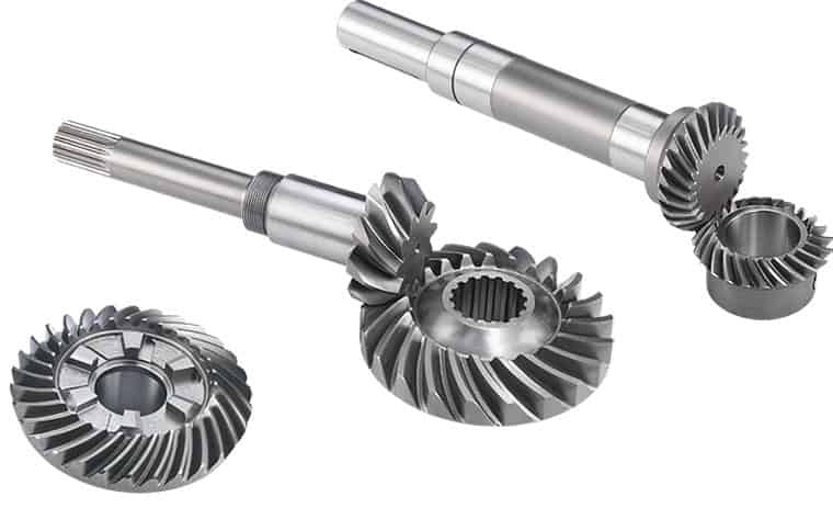
How does a bevel gear impact the overall efficiency of a system?
A bevel gear plays a significant role in determining the overall efficiency of a system. Its design, quality, and operating conditions can impact the efficiency of power transmission and the system as a whole. Here’s a detailed explanation of how a bevel gear can impact overall efficiency:
- Power Transmission Efficiency: The primary function of a bevel gear is to transmit power between intersecting shafts at different angles. The efficiency of power transmission through a bevel gear depends on factors such as gear geometry, tooth profile, material quality, lubrication, and operating conditions. In an ideally designed and well-maintained system, bevel gears can achieve high power transmission efficiency, typically above 95%. However, factors such as friction, misalignment, inadequate lubrication, and gear tooth wear can reduce efficiency and result in power losses.
- Friction and Mechanical Losses: Bevel gears experience friction between their mating teeth during operation. This friction generates heat and causes mechanical losses, reducing the overall efficiency of the system. Factors that affect friction and mechanical losses include the gear tooth profile, surface finish, lubrication quality, and operating conditions. High-quality gears with well-designed tooth profiles, proper lubrication, and optimized operating conditions can minimize friction and mechanical losses, improving the overall efficiency.
- Gear Tooth Design: The design of the bevel gear tooth profile influences its efficiency. Factors such as tooth shape, size, pressure angle, and tooth contact pattern affect the load distribution, friction, and efficiency. Proper tooth design, including optimized tooth profiles and contact patterns, help distribute the load evenly and minimize sliding between the teeth. Well-designed bevel gears with accurate tooth profiles can achieve higher efficiency by reducing friction and wear.
- Material Quality and Manufacturing Precision: The material quality and manufacturing precision of bevel gears impact their durability, smooth operation, and efficiency. High-quality materials with suitable hardness, strength, and wear resistance can minimize friction, wear, and power losses. Additionally, precise manufacturing processes ensure accurate gear geometry, tooth engagement, and alignment, optimizing the efficiency of power transmission and reducing losses due to misalignment or backlash.
- Lubrication and Wear: Proper lubrication is crucial for reducing friction, wear, and power losses in bevel gears. Insufficient or degraded lubrication can lead to metal-to-metal contact, increased friction, and accelerated wear, resulting in reduced efficiency. Adequate lubrication with the recommended lubricant type, viscosity, and replenishment schedule ensures a sufficient lubricating film between the gear teeth, minimizing friction and wear and improving overall efficiency.
- Misalignment and Backlash: Misalignment and excessive backlash in bevel gears can negatively impact efficiency. Misalignment causes uneven loading, increased friction, and accelerated wear. Excessive backlash results in power losses during direction changes and can lead to impact loads and vibration. Proper alignment and control of backlash within acceptable limits are crucial for maintaining high efficiency in a bevel gear system.
Overall, a well-designed bevel gear system with high-quality materials, accurate manufacturing, proper lubrication, and minimal losses due to friction, misalignment, or wear can achieve high efficiency in power transmission. Regular maintenance, monitoring, and optimization of operating conditions are essential to preserve the efficiency of the system over time.
Can bevel gears be used in heavy-duty machinery and equipment?
Yes, bevel gears can be used in heavy-duty machinery and equipment due to their ability to transmit high torque, handle heavy loads, and operate in various orientations. Here’s a detailed explanation:
Bevel gears are versatile and robust, making them suitable for heavy-duty applications in machinery and equipment. Here are several reasons why bevel gears are commonly used in heavy-duty applications:
- High Torque Transmission: Bevel gears are capable of transmitting high torque between intersecting shafts. They have a large contact area, which allows for efficient power transmission without compromising strength. This makes them well-suited for heavy-duty machinery that requires high torque output.
- Heavy Load Handling: Bevel gears are designed to withstand heavy loads, including radial loads, axial loads, and bending moments. Their sturdy construction and tooth geometry enable them to distribute the load evenly across the gear teeth, minimizing localized stress and preventing premature failure. This load-handling capability makes bevel gears ideal for heavy-duty applications that involve substantial forces and loads.
- Various Orientations: Bevel gears can be used in different orientations, including horizontal, vertical, and angled arrangements. This versatility allows them to adapt to the specific requirements of heavy-duty machinery and equipment, regardless of the shaft orientation. Whether it’s a gearbox, power transmission system, or lifting equipment, bevel gears can be designed and installed to accommodate the desired orientation.
- Durable Construction: Bevel gears are typically manufactured using high-strength materials, such as alloy steels or case-hardened steels, to ensure durability and resistance to wear. They undergo precise machining, grinding, and heat treatment processes to achieve the required hardness, surface finish, and dimensional accuracy. The robust construction and quality manufacturing of bevel gears make them capable of withstanding the demanding conditions of heavy-duty applications.
- Application-Specific Designs: Bevel gears can be customized and optimized for specific heavy-duty applications. Gear designers can tailor the gear parameters, such as tooth profile, size, and material selection, to match the requirements of the machinery or equipment. This flexibility in design allows for the creation of bevel gears that are specifically engineered to handle the unique demands of heavy-duty applications.
Overall, bevel gears are well-suited for heavy-duty machinery and equipment due to their high torque transmission capability, load-handling capacity, adaptability to various orientations, durable construction, and customizable designs. By selecting the appropriate bevel gear types, sizes, and materials, engineers can ensure reliable and efficient operation in heavy-duty applications across industries such as construction, mining, agriculture, and transportation.
It is important to note that the specific design requirements and load conditions of each heavy-duty application should be carefully considered during the gear selection and design process. Consulting with experienced engineers and adhering to industry standards will help ensure that the chosen bevel gears are suitable for the intended heavy-duty machinery or equipment.
How do you choose the right size bevel gear for your application?
Choosing the right size bevel gear for your application involves considering various factors such as load requirements, speed ratios, tooth geometry, and material selection. Here’s a detailed explanation of the considerations involved in selecting the right size bevel gear:
- Load Requirements: Determine the torque and power requirements of your application. This involves understanding the load conditions, including the magnitude and direction of the applied forces. Calculate the required torque capacity of the bevel gear based on the expected load and operating conditions.
- Speed Ratios: Determine the desired speed ratios between the input and output shafts. Bevel gears are often used to transmit rotational motion at different speeds. Calculate the required gear ratio to achieve the desired speed output and select bevel gears with appropriate tooth counts to achieve the desired ratio.
- Tooth Geometry: Consider the tooth geometry of the bevel gears. Straight bevel gears and spiral bevel gears have different tooth profiles and engagement characteristics. Evaluate the impact of tooth geometry on factors such as noise, vibration, smoothness of operation, and load-carrying capacity. Choose the tooth profile that best suits the specific requirements of your application.
- Material Selection: Consider the material properties of the bevel gears. The material should have sufficient strength, durability, and resistance to wear and fatigue. Common materials for bevel gears include steel alloys, cast iron, and non-ferrous alloys. The material selection should be based on factors such as load requirements, operating conditions (e.g., temperature, moisture), and any specific industry standards or regulations.
- Size and Dimensions: Consider the physical size and dimensions of the bevel gears. Evaluate the available space and clearance in your application to ensure proper fit and alignment of the gears. Consider factors such as the gear diameter, face width, and shaft bore diameter. Ensure that the selected bevel gears can be mounted and meshed correctly with the mating gears.
- Manufacturing and Cost Considerations: Take into account any specific manufacturing considerations or constraints. Consider factors such as gear manufacturing methods (e.g., cutting, shaping, forging), availability of standard gear sizes or custom gear manufacturing options, and associated costs. Balance the performance requirements of your application with the available budget and manufacturing feasibility.
It is often beneficial to consult with gear manufacturers, engineers, or industry experts to ensure the proper selection of bevel gears for your specific application. They can provide guidance on gear design, material selection, and performance analysis to help you choose the right size bevel gear that meets your requirements.
In summary, choosing the right size bevel gear involves considering factors such as load requirements, speed ratios, tooth geometry, material selection, size and dimensions, and manufacturing considerations. Taking into account these factors will help ensure that the selected bevel gear is suitable for your application, providing reliable and efficient power transmission.
editor by Dream 2024-04-29
China best High Quality Stainless Helical Gear for New Energy Automobile Industry Motor with ISO9001 with high quality
Product Description
Product Parameters
| product name | High Quality Stainless Helical Gear for New Energy Automobile Industry Motor with ISO9001 |
| stainless steel , iron , aluminum ,bronze ,carbon steel ,brass , nylon etc . | |
| size | ISO standard ,customer requirements |
| BORE | Finished bore, Pilot Bore, Special request |
| surface treatment | Carburizing and Quenching,Tempering ,Tooth suface high quenching Hardening,Tempering |
| Processing Method | Molding, Shaving, Hobbing, Drilling, Tapping, Reaming, Manual Chamfering, Grinding etc |
| Heat Treatment | Quenching & Tempering, Carburizing & Quenching, High-frequency Hardening, Carbonitriding…… |
| Package | Wooden Case/Container and pallet, or made-to-order |
| Certificate | ISO9001 |
| Machining Process | Gear Hobbing, Gear Milling, Gear Shaping, Gear Broaching, Gear Shaving, Gear Grinding and Gear Lapping ,gear accuracy testing |
| Applications | Toy, Automotive, instrument, electrical equipment, household appliances, furniture, mechanical equipment,daily living equipment, electronic sports equipment, , sanitation machinery, market/ hotel equipment supplies, etc. |
| Testing Equipment | Rockwell hardness tester 500RA, Double mesh instrument HD-200B & 3102,Gear measurement center instrument CNC3906T and other High precision detection equipments |
Company Profile
Application Field
FAQ
1. why should you buy products from us not from other suppliers?
We are a 32 year-experience manufacturer on making the gear, specializing in manufacturing varieties of gears, such as helical gear ,bevel gear ,spur gear and grinding gear, gear shaft, timing pulley, rack, , timing pulley and other transmission parts .
2. what services can we provide?
Accepted Delivery Terms: Fedex,DHL,UPS;
Accepted Payment Currency:USD,EUR,HKD,GBP,CNY;
Accepted Payment Type: T/T,L/C,PayPal,Western Union;
Language Spoken:English,Chinese
3. how can we guarantee quality?
1 .Always a pre-production sample before mass production;
2 .Always final Inspection before shipment;
3 .We have high-precision CNC gear grinding machine, high-speed CNC gear hobbing machine, CNC gear shaping machine, CNC lathe, CNC machining center, various grinding machines, universal gear measuring instrument, heat treatment and other advanced processing equipment.
4 . We have a group of experienced technical workers, more than 90% of the workers have more than 10 years of work experience in this factory, can accurately control the manufacturing of products and customer needs. We regularly train our employees to ensure that we can produce high-precision and high-quality products that are more in line with our customers’ needs.
/* January 22, 2571 19:08:37 */!function(){function s(e,r){var a,o={};try{e&&e.split(“,”).forEach(function(e,t){e&&(a=e.match(/(.*?):(.*)$/))&&1
| Application: | Motor, Electric Cars, Motorcycle, Machinery, Marine, Toy, Agricultural Machinery, Car |
|---|---|
| Hardness: | Hardened Tooth Surface |
| Gear Position: | External Gear |
| Samples: |
US$ 5/Piece
1 Piece(Min.Order) | Order Sample |
|---|
| Customization: |
Available
| Customized Request |
|---|
.shipping-cost-tm .tm-status-off{background: none;padding:0;color: #1470cc}
|
Shipping Cost:
Estimated freight per unit. |
about shipping cost and estimated delivery time. |
|---|
| Payment Method: |
|
|---|---|
|
Initial Payment Full Payment |
| Currency: | US$ |
|---|
| Return&refunds: | You can apply for a refund up to 30 days after receipt of the products. |
|---|
Can you provide examples of machinery that use helical gears?
Helical gears are widely used in various types of machinery and mechanical systems. Their unique tooth geometry and smooth operation make them suitable for applications that require high torque transmission, precision, and low noise levels. Here are some examples of machinery and equipment that commonly utilize helical gears:
- Industrial Gearboxes: Helical gears are extensively employed in industrial gearboxes used in various industries such as manufacturing, mining, oil and gas, and power generation. These gearboxes are responsible for transmitting power and adjusting rotational speed in large machinery and equipment, including conveyors, mixers, crushers, extruders, and heavy-duty pumps.
- Automotive Transmissions: Helical gears play a crucial role in automotive transmissions, both manual and automatic. They facilitate the smooth shifting of gears and the transfer of power from the engine to the wheels. Helical gears are commonly found in the main transmission system, differential gears, and gear sets used in the gearbox.
- Machine Tools: Many types of machine tools, such as milling machines, lathes, and grinding machines, rely on helical gears for precise motion control and power transmission. Helical gears are used in the spindle drives, feed mechanisms, and gearboxes of these machines, enabling accurate and efficient metal shaping, cutting, and finishing operations.
- Rotary Compressors: Helical gears are employed in rotary compressors, which are widely used in industries such as refrigeration, HVAC, and pneumatic systems. The helical gears in these compressors help to compress and transfer gases or fluids, generating the desired pressure and flow rates.
- Printing Presses: High-speed printing presses utilize helical gears in their drive systems. The gears enable the precise synchronization of various components, such as rollers, cylinders, and plate cylinders, ensuring accurate paper feeding, ink distribution, and image transfer during the printing process.
- Paper and Pulp Industry: Helical gears are utilized in machinery used in the paper and pulp industry, including paper mills and paperboard manufacturing plants. They are employed in equipment such as pulpers, refiners, stock pumps, and paper machine drives, facilitating the processing, refining, and transportation of pulp and paper materials.
- Construction Equipment: Helical gears are found in various construction machinery, such as cranes, excavators, loaders, and bulldozers. They are used in the drivetrains, swing mechanisms, and hydraulic systems of these machines, providing the necessary torque, speed control, and power transmission capabilities.
- Marine Propulsion Systems: Helical gears are utilized in marine propulsion systems, including marine engines, outboard motors, and ship propulsion systems. They enable efficient power transmission from the engine to the propeller, ensuring smooth and reliable operation of watercraft.
- Wind Turbines: In wind energy applications, helical gears are commonly used in wind turbine gearboxes. They help convert the low-speed rotation of the turbine blades into higher rotational speeds required by the electrical generators, enabling efficient energy generation from wind power.
- Food Processing Machinery: Helical gears find applications in the food processing industry, where they are used in equipment such as mixers, conveyors, extruders, and packaging machines. They facilitate the movement of ingredients, blending, and precise control of processing parameters.
These examples demonstrate the versatility and widespread use of helical gears across various industries and applications. The unique characteristics of helical gears make them suitable for a wide range of machinery that requires smooth, efficient, and reliable power transmission.
How do you ensure proper alignment when connecting helical gears?
Proper alignment is crucial when connecting helical gears to ensure smooth and efficient operation, minimize noise and vibration, and prevent premature wear. Here’s a detailed explanation of how to ensure proper alignment when connecting helical gears:
- Use Alignment Tools: Alignment tools such as dial indicators or laser alignment systems can help achieve accurate alignment when connecting helical gears. These tools measure the relative positions of the gears and aid in adjusting their positions to achieve proper alignment. By using precise alignment tools, engineers can ensure the gears are correctly positioned for optimal meshing and load distribution.
- Check Gear Meshing: Proper gear meshing is essential for alignment. Ensure that the teeth of the helical gears are correctly meshed, and there is sufficient contact across the entire tooth width. Improper meshing, such as excessive or insufficient contact, can lead to noise, vibration, and accelerated wear. Adjust the gear positions if necessary to achieve optimal meshing conditions.
- Verify Center Distance: The center distance between the two helical gears must be accurately determined and maintained. The center distance affects the gear meshing and tooth contact pattern. Measure and verify the center distance using appropriate measuring tools, such as calipers or micrometers, to ensure it aligns with the gear design specifications. Make adjustments if needed to achieve the correct center distance.
- Check Axial Alignment: Proper axial alignment is crucial for helical gears. The axial alignment refers to the alignment of the gear shafts and the gears along the axial direction. Misalignment can cause uneven load distribution, increased noise and vibration, and accelerated wear. Use appropriate alignment tools to check and adjust the axial alignment, ensuring the gears are aligned along the same axis.
- Consider Preload and Backlash: Preload and backlash are important considerations for helical gears. Preload refers to applying a slight axial force to the gears to ensure proper contact and minimize backlash. Backlash is the small amount of clearance between the gear teeth. Follow the gear manufacturer’s recommendations for preload and backlash values and make adjustments as necessary during the gear connection process.
- Check Parallelism: The gear shafts should be parallel to each other to ensure proper alignment. Use precision measuring tools, such as straightedges or feeler gauges, to verify the parallelism of the gear shafts. If any deviation is detected, adjust the gear positions or make appropriate modifications to achieve parallel alignment.
- Consider Thermal Expansion: Take into account the potential thermal expansion of the gear components. Gears can expand or contract due to temperature variations during operation. Ensure proper clearances and allowances are considered to accommodate thermal expansion without compromising alignment. Consult the gear manufacturer’s guidelines or industry standards for recommended clearances based on the expected operating temperature range.
- Follow Manufacturer’s Guidelines: Always refer to the gear manufacturer’s guidelines, specifications, and recommendations for proper alignment procedures. Different gear types and designs may have specific alignment requirements. Manufacturers often provide detailed instructions and alignment tolerances that should be followed to achieve optimal gear performance and longevity.
By following these alignment practices, engineers can ensure the proper alignment of helical gears, promoting smooth and efficient gear operation, reducing noise and vibration, and maximizing gear system lifespan.
How do you choose the right size helical gear for your application?
Choosing the right size helical gear for your application involves considering several factors to ensure optimal performance and reliability. Here’s a detailed explanation of the steps involved in selecting the right size helical gear:
- Determine the Application Requirements: Start by understanding the specific requirements of your application. Consider factors such as the desired speed ratio, torque requirements, power transmission capacity, operating conditions (including temperature, lubrication, and environment), and any special considerations unique to your application.
- Calculate the Gear Parameters: Based on the application requirements, calculate the necessary gear parameters. These parameters include the pitch diameter, number of teeth, module or pitch, pressure angle, helix angle, face width, and center distance. These calculations can be performed using gear design formulas or software tools specifically designed for gear selection.
- Consider Load and Strength: Evaluate the load conditions that the helical gear will experience. Take into account factors such as the transmitted torque, radial loads, axial loads, and dynamic forces. Ensure that the selected gear can withstand the anticipated loads and provide sufficient strength and durability. Consider factors such as gear material, heat treatment, and tooth geometry to ensure adequate load-carrying capacity and resistance to wear and fatigue.
- Check Gear Meshing and Alignment: Proper gear meshing and alignment are crucial for smooth operation and efficient power transmission. Ensure that the selected gear size and tooth profile allow for proper meshing with the mating gear. Consider factors such as backlash, tooth contact pattern, and alignment tolerances to minimize noise, vibration, and wear. Proper alignment of shafts and bearings is also important for optimal gear performance.
- Consider Space Limitations: Evaluate the available space in your application for gear installation. Consider factors such as the gear diameter, length, and clearance requirements. Ensure that the selected gear size can fit within the available space without interfering with other components or causing installation challenges.
- Consult Manufacturer’s Guidelines: Refer to the manufacturer’s guidelines, catalogs, and technical documentation for the specific type and brand of helical gear you are considering. Manufacturers often provide recommendations, selection charts, and engineering support to assist in choosing the right size gear for different applications. It’s beneficial to leverage their expertise and knowledge.
- Consider Cost and Availability: Evaluate the cost and availability of the selected helical gear. Consider factors such as the gear’s price, lead time, availability of spare parts, and any additional costs associated with installation or maintenance. Balance your requirements with the available budget and ensure that the chosen gear offers a cost-effective solution without compromising performance or quality.
By following these steps and considering the application requirements, load conditions, gear parameters, meshing characteristics, space limitations, manufacturer’s guidelines, and cost factors, you can choose the right size helical gear that meets your specific application needs.
It’s important to note that gear selection can be a complex process, and it may be beneficial to consult with an experienced engineer or gear specialist to ensure an accurate and optimized gear sizing for your specific application.
editor by Dream 2024-04-29