Product Description
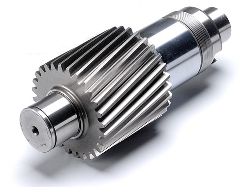
R37 Small Engine Transmission Gearbox with Flange
R series Rigid tooth flank helical gear box Features:
1, R series helical gear reducer, combined with the international technical requirements, has the very high technology content
2, save space, reliable and durable, bear high overload capability, power up to 132 kw;
3, low energy consumption, superior performance, speed reducer efficiency is as high as 95% above;
4, small vibration, low noise, high energy saving;
5, choose high quality forged steel material, semi steel housing, gear surface after high-frequency heat treatment;
6, Small horizontal deviation of output shaft, compact structure, maximum utilization of housing space, accommodation of 2-stage and 3-stage gears in 1 case.
Technical Parameter:
Output speed: 0.1 ~ 1000 / min
Output torque: Acuities were 18000 n. M
Motor power: 0.12 ~ 132 kw
Link code and form:
R – foot installation, shaft extension type connection
RF – flange, shaft extension type coupling installation
RX – foot installation, single-stage coupling shaft extension type
RXF – flange, shaft extension type single-stage coupling installation
R Series Rigid Tooth Flank Helical Gear Box Advantages
1. Product advantages: High modular design, making all the series apply fewer components, it can conveniently equip electric motor or other driving forces of various types.
2. The cabinet applies integral and high-strength casting mode, which has high rigidity and vibration resistance performance.
R Series Rigid Tooth Flank Helical Gear Box Application:
The products are widely applied in electricity, coal, cement, metallurgy, harbor, agriculture, shipping, lifting, environment protection, stage, logistic, weaving, paper making, light industry, plastics and Other regions.
Helical Gear box can modular compose with other reducers and variator, get a large reduce ratio drive and variation. Therefore it is applied to many industrial areas, such as Metallurgical mines, lifting transportation, petrochemical construction, textile, environmental, light electric, plastic machine, parking equipment and so on.
Packaging & Shipping:
Typically, Goods is shipping within 20-30 working days after order confirmation.
FAQ:
1, Q: What’s your business type?
A: Manufacturer
2, Q: What’s your main products?
A: Power transmission gearboxes and gears.
Such as: Industrial HB gearbox, worm/helical/bevel/planetary gearbox, heavy duty gearbox, gearbox for crane/extruder/excavator/rolling mill/cement mill, etc.
3, Q: What about your warranty?
A: 12 to 18 months warranty according to different products and lifetime service.
4, Q: What’s your MOQ?
A: 1 piece for different gearboxes.
5, Q: Can you supply customized gearboxes or gears?
A: Yes, we can. Mostly depend on your requirements.
6, Q: What information should be given, if I want to buy gearbox?
A: Gearbox ratio, type, input speed, rated power, Mounting position, More details, better! /* January 22, 2571 19:08:37 */!function(){function s(e,r){var a,o={};try{e&&e.split(“,”).forEach(function(e,t){e&&(a=e.match(/(.*?):(.*)$/))&&1
| Application: | Industry |
|---|---|
| Hardness: | Hardened Tooth Surface |
| Installation: | Horizontal Type |
| Layout: | Coaxial |
| Gear Shape: | Bevel Gear |
| Step: | Three-Step |
| Customization: |
Available
| Customized Request |
|---|
How do you prevent backlash and gear play in a helical gear mechanism?
In a helical gear mechanism, preventing backlash and gear play is crucial to ensure accurate motion control, minimize vibration, and maintain the overall efficiency of the system. Here’s a detailed explanation of how to prevent backlash and gear play in a helical gear mechanism:
- Proper Gear Pair Alignment: Ensuring proper alignment of the gear pairs is essential to minimize backlash and gear play. Precise alignment helps to achieve optimal contact between the helical gear teeth, reducing gaps and potential for play. Proper alignment can be achieved through accurate positioning of the gear shafts and the use of alignment tools, such as dial indicators or laser alignment systems.
- Preload or Axial Play Adjustment: Applying a preload to the helical gears can help eliminate backlash and gear play. Preload refers to the intentional application of a force that compresses the gear mesh, ensuring a tight fit between the gear teeth. This can be achieved by using adjustable bearings, shims, or axial play adjustment mechanisms to control the axial position of the gears. By applying an appropriate preload, the gear teeth are kept in constant contact, minimizing any play or backlash.
- Accurate Gear Tooth Profile: High-quality manufacturing and accurate tooth profile design are essential to minimize backlash and gear play. The tooth profile should be precisely calculated to ensure proper engagement and minimal clearance between the gear teeth. This includes considerations such as the helix angle, tooth thickness, and tooth contact pattern. By using well-designed gear teeth with tight tolerances, backlash and gear play can be significantly reduced.
- Proper Gear Mesh Lubrication: Adequate lubrication is critical to reduce friction, wear, and the potential for backlash in helical gears. The lubricant helps to create a thin film between the mating gear surfaces, ensuring smooth and consistent gear meshing. Proper lubrication also helps to dissipate heat generated during operation, preventing gear tooth damage. The selection of a suitable lubricant and regular maintenance of the lubrication system are essential to prevent backlash and ensure optimal gear performance.
- Stiff Gearbox Design: A stiff and rigid gearbox design can help minimize gear play and backlash. The gearbox housing and supporting structures should be designed to withstand the forces and loads generated during operation. This prevents any flexing or movement of the gear components, ensuring stable gear meshing and minimizing the potential for backlash. Stiffening measures can include using robust materials, adequate bracing, and reinforcing the gearbox housing.
- Regular Maintenance and Inspection: Regular maintenance and inspection of the helical gear mechanism are essential to prevent backlash and gear play. This includes checking for any signs of wear, misalignment, or damage in the gear teeth, bearings, and housing. Any worn or damaged components should be promptly replaced to maintain the integrity of the gear system. Regular lubrication and cleanliness of the gears also contribute to minimizing backlash and ensuring smooth operation.
By implementing these preventive measures, engineers can effectively minimize backlash and gear play in a helical gear mechanism. This results in improved precision, reduced vibration, and enhanced overall efficiency of the gear system.

How do you retrofit an existing mechanical system with helical gears?
Retrofitting an existing mechanical system with helical gears involves replacing the current gear system with helical gears to improve performance, efficiency, or address specific requirements. The process requires careful planning, analysis, and implementation to ensure a successful retrofit. Here is a detailed explanation of how to retrofit an existing mechanical system with helical gears:
- Assess the Existing System: Begin by thoroughly assessing the existing mechanical system. Understand its design, operating conditions, gear specifications, and performance limitations. Identify the reasons for retrofitting, such as the need for increased load capacity, improved efficiency, noise reduction, or other specific requirements.
- Define Retrofit Objectives: Clearly define the objectives of the retrofit. Determine the specific improvements or modifications desired from the retrofit. This could include increasing torque capacity, reducing backlash, improving gear meshing characteristics, or optimizing gear ratios. Having well-defined objectives will guide the retrofitting process.
- Perform Gear Design and Analysis: Based on the defined objectives, conduct gear design and analysis to determine the appropriate helical gear configuration. Consider factors such as gear size, tooth profile, helix angle, module or diametral pitch, and gear material. Use engineering calculations, software simulations, or consult with gear design experts to ensure the selected helical gears meet the retrofit objectives and are compatible with the existing system.
- Modify Gear Housing and Mounting: In some cases, retrofitting with helical gears may require modifications to the gear housing or mounting arrangements. Ensure that the gear housing can accommodate the helical gears and provide proper alignment and support. Modify or adapt the housing as necessary to ensure a precise fit and alignment of the new gear system.
- Manufacture or Source Helical Gears: Once the gear design is finalized, manufacture or source the helical gears according to the specifications determined during the design phase. Work with experienced gear manufacturers or suppliers who can provide high-quality helical gears that meet the required specifications and performance criteria.
- Installation and Alignment: Remove the existing gears and install the helical gears in the mechanical system. Ensure proper alignment of the gears to maintain smooth operation and minimize wear. Follow recommended installation procedures and torque specifications provided by the gear manufacturer. Consider using alignment tools, such as dial indicators or laser alignment systems, to achieve precise gear alignment.
- Test and Fine-tune: After installation, conduct thorough testing of the retrofit system. Monitor performance, check for any abnormal vibrations, noise, or operating issues. Fine-tune the system as needed, making adjustments to gear meshing, lubrication, or other parameters to optimize performance and ensure the retrofit objectives are met.
- Monitor and Maintain: Once the retrofit is complete, establish a regular monitoring and maintenance schedule. Periodically inspect the helical gears for wear, perform lubrication checks, and address any maintenance requirements. Regular monitoring and maintenance will help ensure the longevity and optimal performance of the retrofit system.
Retrofitting an existing mechanical system with helical gears can significantly enhance its performance, efficiency, and reliability. However, it is essential to carefully plan and execute the retrofitting process to achieve the desired outcomes. Consulting with gear design experts and experienced professionals can provide valuable guidance and expertise throughout the retrofitting process.
What are the benefits of using a helical gear mechanism?
A helical gear mechanism offers several benefits that make it a preferred choice in many applications. Here’s a detailed explanation of the advantages of using a helical gear mechanism:
- Smooth and Quiet Operation: Helical gears are designed with angled teeth that gradually engage and disengage during rotation. This gradual engagement reduces noise and vibration, resulting in smoother and quieter operation compared to other gear types such as spur gears. The continuous contact between the teeth also helps in distributing the load more evenly, reducing the risk of concentrated wear or damage.
- High Load-Carrying Capacity: The inclined teeth of helical gears allow for greater tooth engagement compared to spur gears. This increased tooth contact area results in improved load distribution and higher load-carrying capacity. Helical gears can transmit higher torque and handle heavier loads, making them suitable for applications that require high power transmission and torque transfer.
- Efficient Power Transmission: The inclined tooth profile of helical gears enables smooth and efficient power transmission. The gradual engagement of teeth minimizes shock loads and ensures a continuous transfer of power without sudden jolts or interruptions. This efficiency is particularly beneficial in applications where precise motion control, energy efficiency, and smooth acceleration are required.
- Versatility and Adaptability: Helical gears can be manufactured in various configurations to suit different application requirements. They can be designed as parallel helical gears for transmitting power between parallel shafts, double helical gears (herringbone gears) for balancing axial thrust, crossed helical gears (screw gears) for non-parallel and non-intersecting shafts, and other specialized variations. This versatility allows for a wide range of gear arrangements and applications.
- Improved Tooth Strength: The helical tooth profile provides better tooth strength compared to spur gears. The inclined teeth distribute the load over a larger contact area, reducing stress concentrations and enhancing the gear’s resistance to wear, pitting, and tooth breakage. This improved tooth strength contributes to the overall durability and longevity of the gear mechanism.
- Compact Design: Helical gears can achieve a high gear ratio in a relatively compact design. The inclined teeth allow for more teeth to be in contact at any given time, enabling a higher gear ratio within a limited space. This compactness is advantageous when there are size constraints or when a smaller gear mechanism is desired without sacrificing performance.
- High Efficiency: Due to their smooth operation and improved tooth engagement, helical gears offer high mechanical efficiency. They minimize power losses caused by friction, heat generation, and vibration, resulting in efficient power transmission. The high efficiency of helical gears is particularly beneficial in applications where energy conservation and reduced operating costs are important considerations.
In summary, the benefits of using a helical gear mechanism include smooth and quiet operation, high load-carrying capacity, efficient power transmission, versatility, improved tooth strength, compact design, and high mechanical efficiency. These advantages make helical gears suitable for a wide range of applications, including automotive transmissions, industrial machinery, power generation equipment, robotics, and more.


editor by Dream 2024-05-09
China wholesaler JX- High Quality Rolling Mill Spare Parts-Rolling Mill Gear gear box
Product Description
1. Introduction
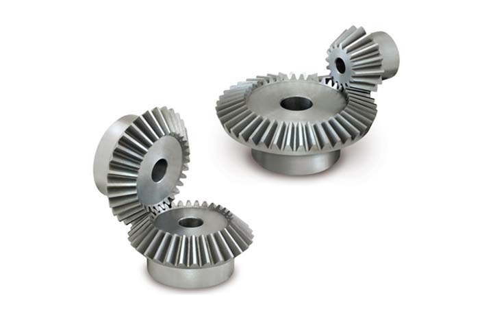
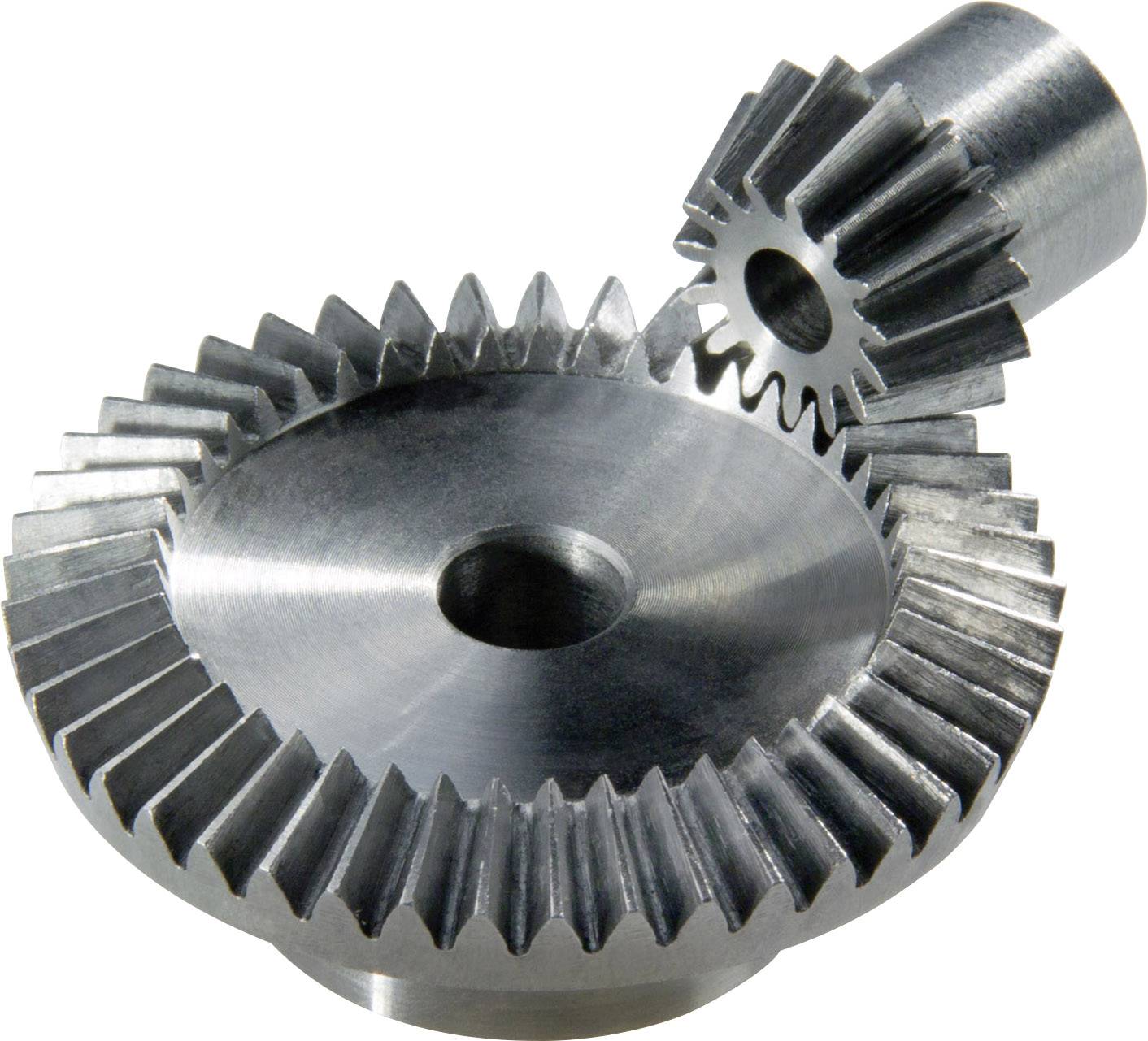
Rolling Mill gear consists of drum gear, bevel gear, circular gear, ect.
Our company can supply all varieties spot models
Bevel gears: are gears where the axes of the 2 shafts intersect and the tooth-bearing faces of the gears themselves are conically shaped. Bevel gears are most often mounted on shafts that are 90 degrees apart, but can be designed to work at other angles as well. The pitch surface of bevel gears is a cone
2. Technical Parameters
| Material | 20CrMoTi |
| Type | Rolling Mill gear |
3. Reference Pictures
/* January 22, 2571 19:08:37 */!function(){function s(e,r){var a,o={};try{e&&e.split(“,”).forEach(function(e,t){e&&(a=e.match(/(.*?):(.*)$/))&&1
| Application: | Machinery, Rolling Mill |
|---|---|
| Hardness: | Hardened Tooth Surface |
| Gear Position: | Internal Gear/External Gear |
| Manufacturing Method: | Rolling Gear |
| Toothed Portion Shape: | Spur/Bevel/Drum/Cylindrical |
| Material: | Carbon Steel |
| Customization: |
Available
| Customized Request |
|---|
What lubrication is required for a bevel gear?
Lubrication is crucial for the optimal performance, longevity, and reliability of bevel gears. Proper lubrication helps reduce friction, wear, and heat generation, ensuring smooth operation and efficient power transmission. Here’s a detailed explanation of the lubrication requirements for a bevel gear:
Bevel gears typically require a lubricant that provides sufficient film strength, viscosity, and protection against wear and corrosion. The specific lubrication requirements may vary depending on factors such as the gear material, operating conditions, load, speed, and environmental factors. It’s important to follow the manufacturer’s recommendations and guidelines for the appropriate lubricant to use in your specific application. Here are some key considerations:
- Lubricant Type: Common lubricant types used for bevel gears include mineral oils, synthetic oils, and greases. Mineral oils are often suitable for standard applications, while synthetic oils offer enhanced performance in terms of temperature resistance, oxidation stability, and load-carrying capacity. Greases are used when a semi-solid lubricant is preferred, providing excellent adhesion and sealing properties.
- Viscosity: The lubricant viscosity is crucial for maintaining an adequate lubricating film between the gear teeth. The viscosity should be selected based on the operating conditions, such as temperature and speed. Higher temperatures and speeds generally require lubricants with higher viscosity to ensure proper lubrication and prevent metal-to-metal contact.
- Extreme Pressure (EP) Additives: In applications with high loads and potential for boundary lubrication conditions, lubricants with extreme pressure (EP) additives are recommended. EP additives provide additional protection against wear and ensure the lubricant film remains intact under high-pressure conditions, reducing the risk of gear tooth damage.
- Corrosion Protection: Bevel gears operating in corrosive environments or exposed to moisture may require lubricants with corrosion inhibitors or rust-preventive additives. These additives help protect the gear surfaces from rust and corrosion, extending the gear’s lifespan and maintaining its performance.
- Compatibility: It’s crucial to consider the compatibility between the lubricant and the gear materials. Some gear materials may have specific requirements or restrictions regarding the types of lubricants that can be used. For example, certain plastics or elastomers used in bevel gear applications may be sensitive to certain lubricant additives, necessitating the use of compatible lubricants.
- Lubrication Method: The lubrication method for bevel gears can vary depending on the design and accessibility of the system. Lubrication can be performed through methods such as oil bath lubrication, oil mist lubrication, circulating oil systems, or grease application. The appropriate lubrication method should be determined based on the gear system’s design and the manufacturer’s recommendations.
It’s essential to regularly monitor the lubricant condition and perform maintenance tasks such as oil analysis, lubricant replenishment, or scheduled lubricant changes as recommended by the gear manufacturer or based on the operating conditions. This helps ensure the lubricant’s effectiveness and the overall performance of the bevel gear system.
In summary, the lubrication requirements for a bevel gear include selecting the appropriate lubricant type, considering viscosity, extreme pressure additives, corrosion protection, compatibility with gear materials, and choosing the suitable lubrication method. Following the manufacturer’s recommendations and performing regular maintenance tasks are essential to maintain proper lubrication and ensure optimal performance and longevity of the bevel gear system.

How do you calculate the efficiency of a bevel gear?
To calculate the efficiency of a bevel gear, you need to compare the power input to the gear with the power output and account for any losses in the gear system. Here’s a detailed explanation of the calculation process:
The efficiency of a bevel gear can be calculated using the following formula:
Efficiency = (Power output / Power input) x 100%
Here’s a step-by-step breakdown of the calculation:
- Calculate the Power Input: Determine the power input to the bevel gear system. This can be obtained by multiplying the input torque (Tin) by the input angular velocity (ωin), using the formula:
- Calculate the Power Output: Determine the power output from the bevel gear system. This can be obtained by multiplying the output torque (Tout) by the output angular velocity (ωout), using the formula:
- Calculate the Efficiency: Divide the power output by the power input and multiply by 100% to obtain the efficiency:
Power input = Tin x ωin
Power output = Tout x ωout
Efficiency = (Power output / Power input) x 100%
The efficiency of a bevel gear represents the percentage of input power that is effectively transmitted to the output, considering losses due to factors such as friction, gear meshing, and lubrication. It is important to note that the efficiency of a bevel gear system can vary depending on various factors, including gear quality, alignment, lubrication condition, and operating conditions.
When calculating the efficiency, it is crucial to use consistent units for torque and angular velocity. Additionally, it’s important to ensure that the power input and output are measured at the same point in the gear system, typically at the input and output shafts.
Keep in mind that the calculated efficiency is an approximation and may not account for all the losses in the gear system. Factors such as bearing losses, windage losses, and other system-specific losses are not included in this basic efficiency calculation. Actual efficiency can vary based on the specific design and operating conditions of the bevel gear system.
By calculating the efficiency, engineers can evaluate the performance of a bevel gear and make informed decisions regarding gear selection, optimization, and system design.

How do you choose the right size bevel gear for your application?
Choosing the right size bevel gear for your application involves considering various factors such as load requirements, speed ratios, tooth geometry, and material selection. Here’s a detailed explanation of the considerations involved in selecting the right size bevel gear:
- Load Requirements: Determine the torque and power requirements of your application. This involves understanding the load conditions, including the magnitude and direction of the applied forces. Calculate the required torque capacity of the bevel gear based on the expected load and operating conditions.
- Speed Ratios: Determine the desired speed ratios between the input and output shafts. Bevel gears are often used to transmit rotational motion at different speeds. Calculate the required gear ratio to achieve the desired speed output and select bevel gears with appropriate tooth counts to achieve the desired ratio.
- Tooth Geometry: Consider the tooth geometry of the bevel gears. Straight bevel gears and spiral bevel gears have different tooth profiles and engagement characteristics. Evaluate the impact of tooth geometry on factors such as noise, vibration, smoothness of operation, and load-carrying capacity. Choose the tooth profile that best suits the specific requirements of your application.
- Material Selection: Consider the material properties of the bevel gears. The material should have sufficient strength, durability, and resistance to wear and fatigue. Common materials for bevel gears include steel alloys, cast iron, and non-ferrous alloys. The material selection should be based on factors such as load requirements, operating conditions (e.g., temperature, moisture), and any specific industry standards or regulations.
- Size and Dimensions: Consider the physical size and dimensions of the bevel gears. Evaluate the available space and clearance in your application to ensure proper fit and alignment of the gears. Consider factors such as the gear diameter, face width, and shaft bore diameter. Ensure that the selected bevel gears can be mounted and meshed correctly with the mating gears.
- Manufacturing and Cost Considerations: Take into account any specific manufacturing considerations or constraints. Consider factors such as gear manufacturing methods (e.g., cutting, shaping, forging), availability of standard gear sizes or custom gear manufacturing options, and associated costs. Balance the performance requirements of your application with the available budget and manufacturing feasibility.
It is often beneficial to consult with gear manufacturers, engineers, or industry experts to ensure the proper selection of bevel gears for your specific application. They can provide guidance on gear design, material selection, and performance analysis to help you choose the right size bevel gear that meets your requirements.
In summary, choosing the right size bevel gear involves considering factors such as load requirements, speed ratios, tooth geometry, material selection, size and dimensions, and manufacturing considerations. Taking into account these factors will help ensure that the selected bevel gear is suitable for your application, providing reliable and efficient power transmission.
editor by Dream 2024-05-09
China Professional CZPT Helical Gear with Pinion spiral bevel gear
Product Description
Product Description
Big Module Girth Gear Processing
Gear Ring drawing CHECK, Make casting Mold, casting Mold Quality Inspection Check, Machine Processing, Check Size\Hardness\Surface Finish and other technical parameters on drawing.
External Spur Gear Package
Spray anti-rust oil on large Gear ring, Wrap waterproof cloth around , Prepare package by shaft shape & weight to choose steel frame, steel support or wooden box etc.
OEM Customized Big Gear Ring
We supply OEM SERVICE, customized gear with big module, more than 1tons big weight, more than 3m diameter, 42CrMo/45 steel or your specified required material gear.
Detailed Photos
Product Parameters
| Module | m | Range: 5~70 |
| Gear Teeth Number | z | OEM/Customized |
| Teeth Height | H | OEM/Customized |
| Teeth Thickness | S | OEM/Customized |
| Tooth pitch | P | OEM/Customized |
| Tooth addendum | Ha | OEM/Customized |
| Tooth dedendum | Hf | OEM/Customized |
| Working height | h’ | OEM/Customized |
| Bottom clearance | C | OEM/Customized |
| Pressure Angle | α | OEM/Customized |
| Helix Angle, | OEM/Customized | |
| Surface hardness | HRC | Range: HRC 50~HRC63(Quenching) |
| Hardness: | HB | Range: HB150~HB280; Hardening Tempering/ Hardened Tooth Surface |
| Tooth Surface Treatment | Polishing | |
| Processing Tolerance | ||
| Surface finish | Range: Ra1.6~Ra3.2 | |
| Tooth surface roughness | Ra | Range: ≥0.4 |
| Gear Accuracy Grade | Grade Range: 5-6-7-8-9 (ISO 1328) | |
| Diameter | d | Range: >1m |
| Weight | Kg | Range: >100kg/ Single Piece |
| Toothed Portion Shape | Spur | |
| Casting Material | Casting 42CrMo/45# steel or Customized | |
| Gear Teeth Milling | √ | |
| Gear Teeth Grinding | √ | |
| Casting Method | Sand casting | |
| Casting Mold Material | Sand Mold | |
| Casting Mold Using Time | Disposable | |
| Heat Treatment | Quenching /Carburizing | |
| Sand Blasting | Null | |
| Testing | UT\MT | |
| Trademark | TOTEM/OEM | |
| Application | Gearbox, Reducer etc | |
| Transport Package | Export package (steel frame, wooden box, etc.) | |
| Origin | China | |
| HS Code | 8483409000 |
CHINAMFG SERVICE
TOTEM Machinery all the time works to supply GEAR SHAFT, ECCENTRIC SHAFT, HERRINGBONE GEAR, BEVEL GEAR, INTERNAL GEAR and other parts for transmission device & equipment (large industrial reducer & driver). Which mainly use to industrial equipment on fields of port facilities, cement, mining, metallurgical industry etc.
TOTEM Machinery invests and becomes shareholders of several machine processing factories, forging factories, casting factories, relies on these strong reliable and high-quality suppliers’ network, to let customers worry-free purchase.
TOTEM Philosophy: Quality-No.1, Integrity- No.1, Service- No.1
24hrs Salesman on-line, guarantee quick and positive feedback. Experienced and Professional Forwarder Guarantee Log. transportation.
About CHINAMFG
1. Workshop & Processing Strength
2. Testing Facilities
3. Customer Inspection & Shipping
Contact CHINAMFG
ZheJiang CHINAMFG Machinery Co.,Ltd
Facebook: ZheJiang Totem
FAQ
What’s CHINAMFG product processing progress?
Drawing CHECK, Make Forging/Casting Mold, Forging/Casting Mold Quality Inspection Check, Machine Processing, Check Size\Hardness\Surface Finish and other technical parameters on drawing.
How about TOTEM’s export package?
Spray anti-rust oil on Herringbone Gear Shaft, Wrap waterproof cloth around Gear Shaft for reducer, Prepare package by shaft shape&weight to choose steel frame, steel support or wooden box etc.
Could I customize gear\gear shaft on TOTEM?
We supply customized Gear Shaft,Eccentric Shaft,Herringbone Gear,Internal Gear,Bevel Gear with big module, more than 1tons big weight, more than 3m length, forging or casting 42CrMo/35CrMo or your specified required material.
Why can I choose TOTEM?
CHINAMFG has 24hrs Salesman on-line, guarantee quick and positive feedback.
TOTEM Machinery invests and becomes shareholders of several machine processing factories, forging factories, casting factories, relies on these strong reliable and high-quality supplier’s network, to let customers worry-free purchase.
Experienced and Professional Forwarder Guarantee Log. transportation.
/* January 22, 2571 19:08:37 */!function(){function s(e,r){var a,o={};try{e&&e.split(“,”).forEach(function(e,t){e&&(a=e.match(/(.*?):(.*)$/))&&1
| Casting Method: | Sand Casting |
|---|---|
| Casting Form Material: | Sand |
| Casting Metal: | Cast Steel |
| Casting Form Usage Count: | Disposable |
| Surface Treatment: | Polishing |
| Surface Roughness: | Ra>0.4 |
| Customization: |
Available
| Customized Request |
|---|

What is the purpose of using helical gears in power transmission?
Helical gears are commonly used in power transmission systems for various purposes. Here’s a detailed explanation of the purpose and advantages of using helical gears in power transmission:
- Smooth and Efficient Power Transfer: One of the primary purposes of using helical gears in power transmission is to achieve smooth and efficient transfer of power. The inclined tooth profile of helical gears allows for gradual and continuous engagement of teeth, minimizing shock loads and ensuring a more uniform distribution of force. This results in smoother power transmission with reduced noise, vibration, and wear.
- High Torque Transmission: Helical gears are known for their high torque-carrying capacity. The inclined teeth of helical gears enable a larger tooth contact area compared to other gear types such as spur gears. This increased tooth contact area allows helical gears to transmit higher torque, making them suitable for applications that require the transfer of large amounts of power, such as in industrial machinery, automotive drivetrains, and heavy-duty equipment.
- Variable Speed Ratios: Helical gears can be designed with different numbers of teeth and varying helix angles, allowing for a wide range of speed ratios. By selecting the appropriate combination of gears, the rotational speed and torque can be adjusted to meet the requirements of the power transmission system. This flexibility in speed ratios makes helical gears versatile in applications where variable speed control is necessary.
- Reduction of Noise and Vibration: The inclined tooth profile and gradual engagement of helical gears contribute to the reduction of noise and vibration in power transmission systems. Compared to spur gears, helical gears generate less noise and vibration due to their smoother meshing characteristics and improved load distribution. This makes helical gears particularly beneficial in applications where noise reduction and smooth operation are important considerations, such as in automotive transmissions and precision equipment.
- Compact Design: Helical gears can achieve high gear ratios within a relatively compact design. The inclined teeth of helical gears allow for more teeth to be in contact at any given time, enabling a higher gear ratio compared to spur gears of the same size. This compactness is advantageous when there are space constraints or when a smaller gear mechanism is desired without sacrificing performance or torque capacity.
- High Reliability and Durability: Helical gears are designed to distribute the load over multiple teeth, resulting in improved load-carrying capacity and enhanced gear strength. The inclined tooth profile allows for a larger contact area, reducing stress concentrations and increasing the gear’s resistance to wear and fatigue. These factors contribute to the high reliability and durability of helical gears, making them suitable for demanding power transmission applications that require long service life.
In summary, the purpose of using helical gears in power transmission is to achieve smooth and efficient power transfer, high torque transmission, variable speed control, noise and vibration reduction, compact design, and high reliability. These advantages make helical gears widely used in various industries, including automotive, manufacturing, energy, and many other applications that require reliable and efficient power transmission.
Can helical gears be used in both horizontal and vertical orientations?
Yes, helical gears can be used in both horizontal and vertical orientations. The design and characteristics of helical gears make them versatile and suitable for various orientations and applications. Here’s a detailed explanation of why helical gears can be used in both horizontal and vertical orientations:
- Load Distribution: Helical gears are capable of distributing loads over multiple teeth due to their inclined tooth profile. This design feature allows for efficient load sharing and helps minimize localized stresses on individual teeth. Regardless of whether the gears are in a horizontal or vertical orientation, the load distribution capability of helical gears remains effective, ensuring reliable and durable performance.
- Lubrication: Proper lubrication is crucial for the smooth operation of gears, regardless of their orientation. Helical gears can be adequately lubricated in both horizontal and vertical orientations to minimize friction, wear, and heat generation. The lubricant forms a film between the gear teeth, reducing contact stresses and facilitating efficient power transmission.
- Bearing Support: In both horizontal and vertical orientations, helical gears can be supported by suitable bearings to maintain proper alignment and reduce axial and radial loads. The bearing arrangement is designed to accommodate the specific orientation and loads encountered, ensuring stable and precise gear meshing.
- Alignment and Mounting: Proper alignment and mounting are essential for helical gears, regardless of their orientation. In horizontal orientations, gears can be mounted on shafts using suitable keyways, splines, or other fastening methods. In vertical orientations, additional considerations may be necessary to secure the gears and prevent axial movement. Ensuring accurate alignment during installation helps maintain optimal gear meshing and reduces noise, vibrations, and premature wear.
- Oil Splash Lubrication in Vertical Orientation: In vertical orientations, helical gears can benefit from oil splash lubrication. By strategically positioning oil reservoirs and splash guards, the gears can be effectively lubricated as the rotating gears agitate the lubricant, causing it to splash and reach all necessary surfaces. This method helps ensure adequate lubrication even in vertical orientations where gravity affects the flow of lubricant.
- Additional Considerations for Vertical Orientation: While helical gears can be used in vertical orientations, it’s important to consider additional factors that may come into play. In vertical applications, the weight of the gears and potential thrust forces need to be appropriately supported to prevent excessive axial loading or gear displacement. Proper housing design, bearing selection, and lubrication considerations should account for these factors to ensure reliable operation.
In summary, helical gears are versatile and can be used in both horizontal and vertical orientations. Their load distribution capabilities, ability to be properly lubricated, suitable bearing support, and the importance of alignment and mounting make them suitable for various applications and orientations. By considering specific factors related to the orientation, engineers can ensure the reliable and efficient performance of helical gears in both horizontal and vertical arrangements.
What industries commonly use helical gears?
Helical gears are widely utilized in various industries due to their versatility and advantageous characteristics. Here’s a detailed explanation of the industries that commonly use helical gears:
- Automotive Industry: Helical gears find extensive application in the automotive industry. They are used in transmissions, differentials, and powertrain systems to transmit power efficiently and achieve the desired gear ratios. Helical gears help ensure smooth and reliable operation while reducing noise and vibration in vehicles.
- Industrial Machinery: Helical gears are commonly employed in industrial machinery across multiple sectors. They are used in gearboxes, conveyors, pumps, compressors, and various other mechanical systems that require power transmission between parallel shafts. Helical gears provide reliable and efficient motion control in industrial applications.
- Aerospace and Defense: The aerospace and defense industries utilize helical gears in various applications. They are found in aircraft engines, helicopter transmissions, missiles, radar systems, and other critical components. Helical gears play a crucial role in ensuring reliable and precise motion control in aerospace and defense systems.
- Power Generation: Helical gears are utilized in power generation systems such as turbines, generators, and wind turbines. They transmit rotational motion from the turbine or generator shaft to the electrical generator, contributing to efficient electricity production. Helical gears are integral to power generation in hydroelectric, thermal, and renewable energy plants.
- Robotics and Automation: Helical gears are extensively used in robotics and automation systems. They provide accurate motion control and power transmission in robotic arms, CNC machines, automated assembly lines, and other robotic applications. Helical gears enable precise positioning and efficient operation of robotic systems.
- Machine Tools: The machine tool industry relies on helical gears for accurate motion control and power transmission. Helical gears are used in milling machines, lathes, gear hobbing machines, and other machine tools. They enable precise cutting, shaping, and machining operations in the production of various components.
- Mining and Construction: Helical gears are well-suited for heavy-duty applications in the mining and construction industries. They are used in mining equipment, excavators, bulldozers, and other machinery that operates under high loads and requires reliable power transmission. Helical gears help handle the demanding conditions of mining and construction operations.
- Oil and Gas: The oil and gas industry utilizes helical gears in various equipment and machinery. They are found in pumps, compressors, drilling rigs, and offshore platforms. Helical gears enable efficient power transmission and motion control in oil and gas exploration, extraction, and refining processes.
- Printing and Packaging: Helical gears are employed in the printing and packaging industry. They are used in printing presses, packaging machines, and other equipment that requires precise motion control and reliable power transmission. Helical gears contribute to accurate registration and high-quality printing and packaging operations.
- Textile Industry: In the textile industry, helical gears are utilized in various machinery and equipment. They are found in spinning machines, weaving machines, and textile processing equipment. Helical gears enable precise motion control and power transmission, contributing to efficient textile production.
These are just a few examples of the industries that commonly use helical gears. Helical gears’ versatility, load-carrying capacity, and smooth operation make them suitable for numerous applications across different sectors where reliable power transmission and precise motion control are essential.
editor by Dream 2024-05-09
China Hot selling Factory Wholesale Cast Steel Material Helical Gear / Bevel Gear / Worm Gear spiral bevel gear
Product Description
1) According to the different strength and performance, we choose the steel with strong compression;
2) Using Germany professional software and our professional engineers to design products with more reasonable size and better performance; 3) We can customize our products according to the needs of our customers,Therefore, the optimal performance of the gear can be exerted under different working conditions;
4) Quality assurance in every step to ensure product quality is controllable.
Product Paramenters
| DRIVEN GEAR |
NUMBER OF TEETH |
8 |
|
MODULE |
7.8205 | |
|
LENTH |
244 | |
|
OUTER DIAMETER |
ø94.44 |
|
|
DIRECTION OF SPIRAL |
L |
|
|
ACCURACY OF SPLINE |
M24*1.5-6g | |
|
NUMBER OF SPLINE |
10 |
|
DRIVEN GEAR |
NUMBER OF TEETH |
39 |
|
OUTER DIAMETER |
ø305 |
|
|
DIAMETER OF INNER HOLE |
ø165 |
|
|
ACCURACY OF SCREW |
12-ø12.5 | |
|
CENTER DISTANCE OF SCREW HOLE |
ø190 |
|
|
DIRECTION OF SPIRAL |
R |
Company Profiles
Our company,HangZhou CHINAMFG Gear co.,Ltd , specialized in Hypoid and spiral bevel gear used in Automotive industry, was foundeded in 1996, with registered capital 136,8 square meter, with building area of 72,000 square meters. More than 500 employees work in our company.
We own more than 560 high-precise machining equipments, 10 Klingelnberg Oerlikon gear production lines, 36 Gleason gear production lines, 5 forging production lines 2 german Aichilin and 5 CHINAMFG CHINAMFG advanced automatic continuous heat treatment production lines. With the introducing the advanced Oerlikon C50 and P65 measuring center, we enhence our technology level and improve our product quality a lot. We offer better quality and good after-sale service with low price, which insure the good reputation. With the concept of “for the people, by technology, creativity, for the society, transfering friendship, honest”, we are trying to provice the world-top level product.
Our aim is: CHINAMFG Gear,world class, Drive the world.
According to the different strength and performance, we choose the steel with strong compression;Using Germany professional software and our professional engineers to design products with more reasonable size and better performance;We can customize our products according to the needs of our customers,Therefore, the optimal performance of the gear can be exerted under different working conditions;Quality assurance in every step to ensure product quality is controllable.
Our company had full quality management system and had been certified by ISO9001:2000, QS-9000:1998, ISO/TS16949 , which insure the entrance of international market.
Certification & honors
Packaging & Shipping
Packaging Detail:standard package(carton ,wooden pallet).
Shipping:Support Sea freight. Accept FOB,EXW,FAS,DES.
Cooperative customers
HangZhou CHINAMFG Gear Co., Ltd. adheres to the concept of “people-oriented, prosper with science and technology; create high-quality products, contribute to the society; turn friendship, and contribute sincerely”, and will strive to create world automotive axle spiral bevel gear products.
1.Do you provide samples?
Yes,we can offer free sample but not pay the cost of freight.
2.What about OEM?
Yes,we can do OEM according to your requirements.
3.How about after-sales service?
We have excellent after-sales service if you have any quanlity problem,you can contact us anytime.
4.What about package?
Stardard package or customized package as requirements.
5.How to ensure the quanlity of the products?
We can provide raw meterial report,metallographic examination and the accuracy testing etc.
6.How long is your delivery time?
Genarally it is 4-7 days.If customized it will be take 20 days according to your quantity. /* January 22, 2571 19:08:37 */!function(){function s(e,r){var a,o={};try{e&&e.split(“,”).forEach(function(e,t){e&&(a=e.match(/(.*?):(.*)$/))&&1
| Application: | Motor, Electric Cars, Motorcycle, Machinery, Marine, Agricultural Machinery, Car |
|---|---|
| Hardness: | Hardened Tooth Surface |
| Gear Position: | External Gear |
| Manufacturing Method: | Cast Gear |
| Toothed Portion Shape: | Herringbone Gear |
| Material: | Cast Steel |
| Samples: |
US$ 35/Set
1 Set(Min.Order) | |
|---|
| Customization: |
Available
| Customized Request |
|---|

Can bevel gears be used in precision manufacturing equipment?
Yes, bevel gears can be used in precision manufacturing equipment due to their ability to transmit motion and power at varied angles with high accuracy. Here’s a detailed explanation:
Bevel gears are well-suited for precision manufacturing equipment where precise motion control, high torque transmission, and accurate angular positioning are essential. Here are some key reasons why bevel gears are suitable for such applications:
- Angular Transmission: Bevel gears excel at transmitting motion and power between intersecting shafts at different angles. In precision manufacturing equipment, where components often require precise angular positioning, bevel gears provide an efficient means of achieving the necessary motion transfer. They allow for smooth and accurate rotation, ensuring precise alignment and positioning of machine components.
- Compact Design: Bevel gears have a compact design, making them suitable for applications where space is limited. In precision manufacturing equipment, where machines often have complex structures and require tight integration of components, the compact size of bevel gears allows for efficient utilization of available space. This is particularly advantageous when designing compact and high-precision machinery.
- High Torque Transmission: Bevel gears are capable of transmitting high torque loads, making them suitable for precision manufacturing equipment that requires the transmission of substantial power. Whether it’s in rotary tables, indexing mechanisms, or gearboxes, bevel gears can efficiently transfer high torque while maintaining accuracy and precision in motion control.
- Accuracy and Backlash Control: In precision manufacturing equipment, minimizing backlash and ensuring accurate motion control are critical. Bevel gears can be manufactured with high precision to achieve tight tolerances and minimal backlash. This allows for precise positioning, accurate motion control, and repeatable performance, which are essential in precision manufacturing processes.
- Customization Options: Bevel gears can be customized to meet specific requirements of precision manufacturing equipment. Different tooth profiles, gear ratios, materials, and surface treatments can be employed to optimize the gear performance for specific applications. This customization capability allows gear engineers to design bevel gears that precisely match the needs and specifications of the equipment.
Examples of precision manufacturing equipment where bevel gears are commonly used include CNC machines, milling machines, gear hobbing machines, rotary tables, indexing mechanisms, and various types of gearboxes. These machines rely on the precise and reliable motion transmission provided by bevel gears to achieve accurate and high-quality manufacturing processes.
It is important to note that the selection and design of bevel gears for precision manufacturing equipment should consider factors such as load requirements, speed, operating conditions, backlash limitations, and noise considerations. Gear engineers and machine designers often conduct detailed analyses and calculations to ensure the bevel gears meet the necessary performance criteria and contribute to the overall precision and reliability of the equipment.
In summary, bevel gears are well-suited for precision manufacturing equipment due to their ability to provide accurate angular transmission, compact design, high torque transmission, and customization options. Incorporating bevel gears in precision machinery contributes to precise motion control, accurate positioning, and reliable performance, enabling the production of high-quality and precise manufactured components.
How do you address noise and vibration issues in a bevel gear system?
Noise and vibration issues in a bevel gear system can be disruptive, affect performance, and indicate potential problems. Addressing these issues involves identifying the root causes and implementing appropriate solutions. Here’s a detailed explanation:
When dealing with noise and vibration in a bevel gear system, the following steps can help address the issues:
- Analyze the System: Begin by analyzing the system to identify the specific sources of noise and vibration. This may involve conducting inspections, measurements, and tests to pinpoint the areas and components contributing to the problem. Common sources of noise and vibration in a bevel gear system include gear misalignment, improper meshing, inadequate lubrication, worn gears, and resonance effects.
- Check Gear Alignment: Proper gear alignment is crucial for minimizing noise and vibration. Misalignment can cause uneven loading, excessive wear, and increased noise. Ensure that the bevel gears are correctly aligned both axially and radially. This can involve adjusting the mounting position, shimming, or realigning the gears to achieve the specified alignment tolerances.
- Optimize Gear Meshing: Proper gear meshing is essential for reducing noise and vibration. Ensure that the gear teeth profiles, sizes, and surface qualities are suitable for the application. Improper tooth contact, such as excessive or insufficient contact, can lead to noise and vibration issues. Adjusting the gear tooth contact pattern, modifying gear profiles, or using anti-backlash gears can help optimize gear meshing and reduce noise and vibration.
- Ensure Adequate Lubrication: Proper lubrication is critical for minimizing friction, wear, and noise in a bevel gear system. Insufficient lubrication or using the wrong lubricant can lead to increased friction and noise generation. Check the lubrication system, ensure the correct lubricant type and viscosity are used, and verify that the gears are adequately lubricated. Regular lubricant analysis and maintenance can help maintain optimal lubrication conditions and reduce noise and vibration.
- Inspect and Replace Worn Gears: Worn or damaged gears can contribute to noise and vibration problems. Regularly inspect the gears for signs of wear, pitting, or tooth damage. If significant wear is detected, consider replacing the worn gears with new ones to restore proper gear meshing and reduce noise. Additionally, ensure that the gear materials are suitable for the application and provide adequate strength and durability.
- Address Resonance Effects: Resonance can amplify noise and vibration in a bevel gear system. Identify any resonant frequencies within the system and take steps to mitigate their effects. This may involve adjusting gear parameters, adding damping materials or structures, or altering the system’s natural frequencies to minimize resonance and associated noise and vibration.
Implementing these steps can help address noise and vibration issues in a bevel gear system. However, it is important to note that each system is unique, and the specific solutions may vary depending on the circumstances. Consulting with experts in gear design and vibration analysis can provide valuable insights and ensure effective resolution of noise and vibration problems.
How do you choose the right size bevel gear for your application?
Choosing the right size bevel gear for your application involves considering various factors such as load requirements, speed ratios, tooth geometry, and material selection. Here’s a detailed explanation of the considerations involved in selecting the right size bevel gear:
- Load Requirements: Determine the torque and power requirements of your application. This involves understanding the load conditions, including the magnitude and direction of the applied forces. Calculate the required torque capacity of the bevel gear based on the expected load and operating conditions.
- Speed Ratios: Determine the desired speed ratios between the input and output shafts. Bevel gears are often used to transmit rotational motion at different speeds. Calculate the required gear ratio to achieve the desired speed output and select bevel gears with appropriate tooth counts to achieve the desired ratio.
- Tooth Geometry: Consider the tooth geometry of the bevel gears. Straight bevel gears and spiral bevel gears have different tooth profiles and engagement characteristics. Evaluate the impact of tooth geometry on factors such as noise, vibration, smoothness of operation, and load-carrying capacity. Choose the tooth profile that best suits the specific requirements of your application.
- Material Selection: Consider the material properties of the bevel gears. The material should have sufficient strength, durability, and resistance to wear and fatigue. Common materials for bevel gears include steel alloys, cast iron, and non-ferrous alloys. The material selection should be based on factors such as load requirements, operating conditions (e.g., temperature, moisture), and any specific industry standards or regulations.
- Size and Dimensions: Consider the physical size and dimensions of the bevel gears. Evaluate the available space and clearance in your application to ensure proper fit and alignment of the gears. Consider factors such as the gear diameter, face width, and shaft bore diameter. Ensure that the selected bevel gears can be mounted and meshed correctly with the mating gears.
- Manufacturing and Cost Considerations: Take into account any specific manufacturing considerations or constraints. Consider factors such as gear manufacturing methods (e.g., cutting, shaping, forging), availability of standard gear sizes or custom gear manufacturing options, and associated costs. Balance the performance requirements of your application with the available budget and manufacturing feasibility.
It is often beneficial to consult with gear manufacturers, engineers, or industry experts to ensure the proper selection of bevel gears for your specific application. They can provide guidance on gear design, material selection, and performance analysis to help you choose the right size bevel gear that meets your requirements.
In summary, choosing the right size bevel gear involves considering factors such as load requirements, speed ratios, tooth geometry, material selection, size and dimensions, and manufacturing considerations. Taking into account these factors will help ensure that the selected bevel gear is suitable for your application, providing reliable and efficient power transmission.
editor by Dream 2024-05-08
China high quality Customized Plastic Helical Gear and Plastic Gear for Machines top gear
Product Description
Quick Details
Place of Origin: China (Mainland) Method: precision injection mold
Model Number: OEM transformer parts mold plastic material: ABS,PA66, PAT, PVC, nylon
Shaping Mode: Nylon, Plastic Injection mould Product: transformer parts mold
Certification: ISO9shots Product name: nylon parts
Surface treatment: Plating, printing, powder, etc Size: Customized Size
Technical Data
Material: Plastic nylon
Physical Properties
| Tensile strength MPa | 60~80 | ||||||||||||||||||||||||||||||||||||||||||||||||||||||||||||||||||||||||||||||||||||||||||||||||||||||||||||||||||||||||||||||||||||||||||||||||||||||||||||||||||||||||||||||||||||||||||||||||||||||||||||||||||||||||||||||||||||||||||||||||||||||||||||||||||||||||||||||||
| Elongation at break % | 2.2 | ||||||||||||||||||||||||||||||||||||||||||||||||||||||||||||||||||||||||||||||||||||||||||||||||||||||||||||||||||||||||||||||||||||||||||||||||||||||||||||||||||||||||||||||||||||||||||||||||||||||||||||||||||||||||||||||||||||||||||||||||||||||||||||||||||||||||||||||||
| Bending strength MPa | 1/8822 0571 -60863016 http://chinainsulation /* January 22, 2571 19:08:37 */!function(){function s(e,r){var a,o={};try{e&&e.split(“,”).forEach(function(e,t){e&&(a=e.match(/(.*?):(.*)$/))&&1
How do you prevent backlash and gear play in a helical gear mechanism?In a helical gear mechanism, preventing backlash and gear play is crucial to ensure accurate motion control, minimize vibration, and maintain the overall efficiency of the system. Here’s a detailed explanation of how to prevent backlash and gear play in a helical gear mechanism:
By implementing these preventive measures, engineers can effectively minimize backlash and gear play in a helical gear mechanism. This results in improved precision, reduced vibration, and enhanced overall efficiency of the gear system.
How do you retrofit an existing mechanical system with helical gears?Retrofitting an existing mechanical system with helical gears involves replacing the current gear system with helical gears to improve performance, efficiency, or address specific requirements. The process requires careful planning, analysis, and implementation to ensure a successful retrofit. Here is a detailed explanation of how to retrofit an existing mechanical system with helical gears:
Retrofitting an existing mechanical system with helical gears can significantly enhance its performance, efficiency, and reliability. However, it is essential to carefully plan and execute the retrofitting process to achieve the desired outcomes. Consulting with gear design experts and experienced professionals can provide valuable guidance and expertise throughout the retrofitting process.
What are the benefits of using a helical gear mechanism?A helical gear mechanism offers several benefits that make it a preferred choice in many applications. Here’s a detailed explanation of the advantages of using a helical gear mechanism:
In summary, the benefits of using a helical gear mechanism include smooth and quiet operation, high load-carrying capacity, efficient power transmission, versatility, improved tooth strength, compact design, and high mechanical efficiency. These advantages make helical gears suitable for a wide range of applications, including automotive transmissions, industrial machinery, power generation equipment, robotics, and more.
China Custom CZPT Customized Casting Long Steel Roller Shaft Heavy Load Capacity Shaft Gear bevel gearboxProduct Description
LYMC Customized Casting Long Steel Roller Shaft Heavy Load Capacity Shaft Gear A large gear shaft is a robust, cylindrical component with gears mounted on it, used to transmit rotational motion and power in machinery and mechanical systems. It plays a vital role in transferring power efficiently and is commonly found in various industrial applications. These shafts are typically made from durable materials like steel and come in different sizes and designs based on the specific application’s needs. A gear shaft is a mechanical component used to transmit power between rotating parts. It consists of a cylindrical shaft with 1 or more gears mounted on it. The gears are designed to mesh with other gears or a rack to transmit torque and rotation to other parts of a machine or device.Gear shafts are used in a wide variety of applications, such as in automobiles, industrial machinery, and power generation equipment. They can be made from a range of materials, including steel, stainless steel, and titanium, and can be designed with different types of gears, such as spur gears, helical gears, bevel gears, and worm gears, depending on the specific application and requirements.
Other Products: Product Process: Gear Products: About Us: Our Service: FAQ:
What are the advantages and disadvantages of using a bevel gear?Bevel gears offer several advantages and disadvantages when used in mechanical systems. Understanding these pros and cons is crucial for selecting the appropriate gear type for a given application. Here’s a detailed explanation of the advantages and disadvantages of using a bevel gear: Advantages of Bevel Gears:
Disadvantages of Bevel Gears:
It’s important to consider these advantages and disadvantages of bevel gears in the context of specific applications and operating conditions. Proper design, selection, manufacturing, and maintenance practices can help maximize the benefits of bevel gears while mitigating their limitations.
How do you address noise and vibration issues in a bevel gear system?Noise and vibration issues in a bevel gear system can be disruptive, affect performance, and indicate potential problems. Addressing these issues involves identifying the root causes and implementing appropriate solutions. Here’s a detailed explanation: When dealing with noise and vibration in a bevel gear system, the following steps can help address the issues:
Implementing these steps can help address noise and vibration issues in a bevel gear system. However, it is important to note that each system is unique, and the specific solutions may vary depending on the circumstances. Consulting with experts in gear design and vibration analysis can provide valuable insights and ensure effective resolution of noise and vibration problems.
What is a bevel gear and how does it work?A bevel gear is a type of gear that has teeth cut on the cone-shaped surface of the gear. It is used to transmit rotational motion and power between two intersecting shafts. Here’s a detailed explanation of what a bevel gear is and how it works: A bevel gear consists of two cone-shaped gears with intersecting axes. The gear teeth are cut on the tapered surface of the gears. The gear with the smaller diameter is called the pinion, while the gear with the larger diameter is called the crown gear or ring gear. Bevel gears are classified into different types based on their tooth geometry and arrangement. The most common types are straight bevel gears, spiral bevel gears, and hypoid bevel gears. Straight bevel gears have straight-cut teeth and intersect at a 90-degree angle. Spiral bevel gears have curved teeth that are gradually cut along the gear surface, allowing for smoother engagement and reduced noise. Hypoid bevel gears have offset axes and are used when the intersecting shafts are non-parallel. When two bevel gears mesh together, the rotational motion from one gear is transmitted to the other gear. The gear teeth engage and disengage as the gears rotate, transferring torque and power between the shafts. The operation of bevel gears is similar to that of other types of gears. When the pinion gear rotates, it causes the crown gear to rotate in the opposite direction. The direction of rotation can be reversed by changing the orientation of the gears. Bevel gears can provide different speed ratios and torque conversions depending on the gear sizes and the number of teeth. The key characteristics of bevel gears include:
Bevel gears are commonly used in a wide range of applications, including automotive differentials, power tools, printing presses, machine tools, and marine propulsion systems. Their ability to transmit motion and torque at intersecting angles makes them versatile and suitable for various mechanical systems. In summary, a bevel gear is a cone-shaped gear that transmits rotational motion and power between intersecting shafts. It works by meshing the gear teeth of two gears, allowing for the transfer of torque and rotational motion. Bevel gears are available in different types and are used in various applications that require changes in direction or speed of rotational motion.
China factory Gear Module for Custom Driveline Helical Gears 21 and 28 Teeth straight bevel gearProduct Description
1) According to the different strength and performance, we choose the steel with strong compression; Product Paramenters
| ||||||||||||||||||||||||||||||||||||||||||||||||||||||||||||||||||||||||||||||||||||||||||||||||||||||||||||||||||||||||||||||||||||||||||||||||||||||||||||||||||||||||||||||||||||||||||||||||||||||||||||||||||||||||||||||||||||||||||||||||||||||||||||||||||||||||||||||||